
NOAA Teacher at Sea
Rosalind Echols
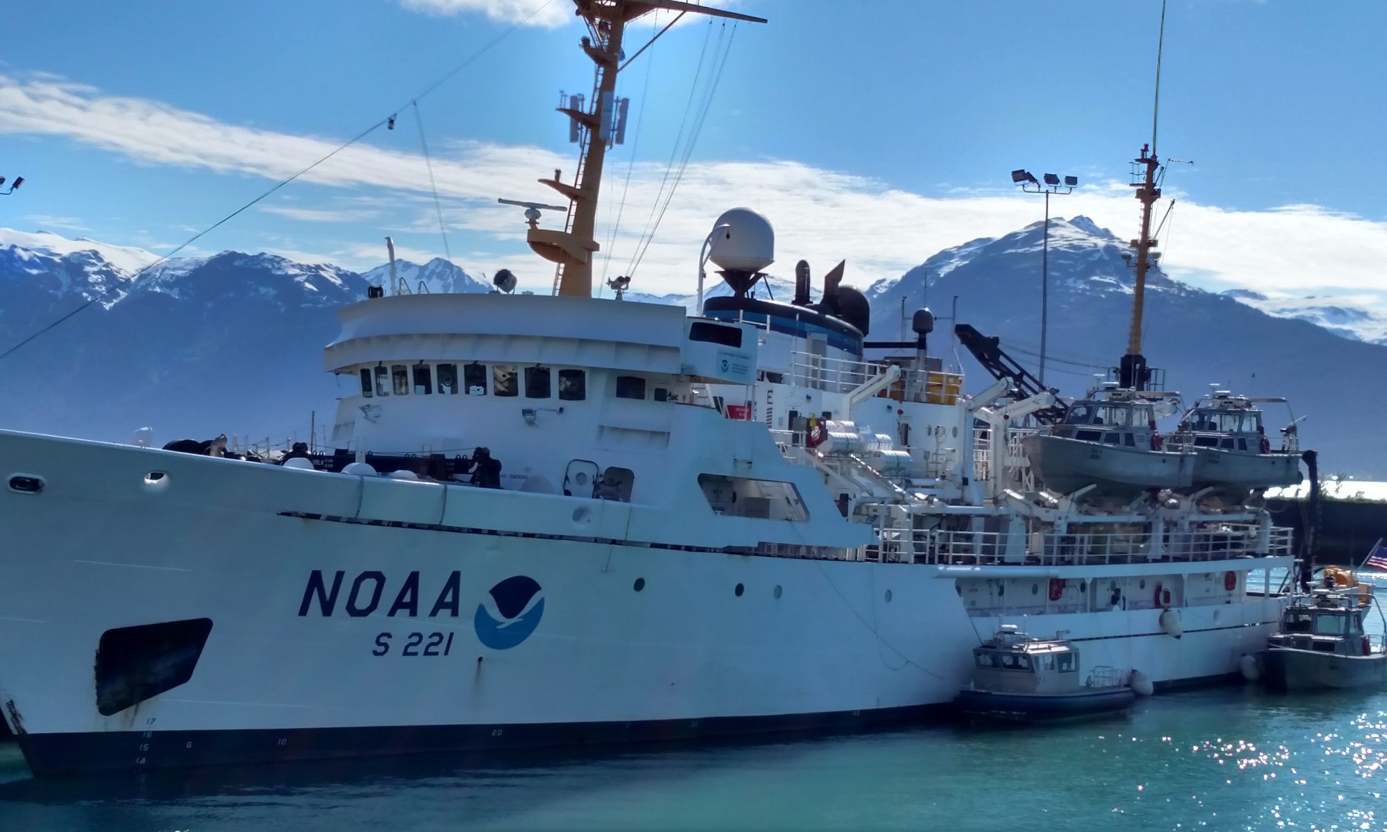
Aboard NOAA Ship Rainier (Ship Tracker)
July 8-25, 2013
Mission: Hydrographic Survey
Geographical Area of Cruise: Shumagin Islands, Alaska
Date: July 19, 2013
Current Location: 54° 49.684 N, 159° 46.604 W
Weather Data from the Bridge: Foggy and overcast, wind 21 knots, 11.5° C
Science and Technology Log:

As the fog horn sounds every two minutes and we sail solitary through the ocean, we are now in full swing surveying the Shumagin Islands, between and around Nagai, Bird, and Chernabura Islands. Unlike the old-time surveyors who used lead lines (lead weight attached to a long string), we are using a multibeam sonar system, which enables us to gather a large quantity of very accurate data in a more efficient and timely fashion.

Sonar, (SOund Navigation And Ranging) uses the principle of sound wave reflection to detect objects in the water. Just as our eyes see the reflection of visible light off of the objects around us to create a visual image, when a sound wave hits something, it reflects off that “thing” and returns to its starting point (the receiver). We can measure the time it takes for a pulse to travel from the Sonar device below the boat to the ocean floor and then back to the receiver on the boat. Using a simple distance=speed * time equation, we can get the water depth at the spot where each beam is reflected.
The skiff that we use for the shoreline activities discussed in the last post has a single-beam sonar system that directs a pulse straight down beneath the hull to get a rough depth estimate. However, for our hydrographic work on the ship and launches, we use a multibeam system that sends 512 sound pulses simultaneously towards the sea floor over a 120° angle. When many sound waves or “beams” are emitted at the same time (called a pulse) in a fan like pattern (called a swath), the reflected information creates a “sound picture” of the objects or surface within that swath range. The actual width of this swath varies with the depth, but with 512 beams per pulse, and sending out between 5-30 pulses every second, we acquire a lot of data. If you piece together many swaths worth of data you get a continuous topographical or physical map of the ocean floor, and thus the depth of the water. For more information about the specific sonar system used aboard the Rainier and its launches, check out the ship page or the NOAA page about their hydrography work.


In order to understand the complexities of sonar, it is important to understand the properties of sound. Sound is a pressure wave that travels when molecules collide with each other. We know that sound can travel in air, because we experience this every day when we talk to each other, but it can also travel in liquids and solids (which whales rely on to communicate). As a general rule, sound travels much faster in liquids and solids than in air because the molecules in liquids and solids are closer together and therefore collide more often, passing on the vibration at a faster rate. (The average speed of sound in air is about 343 meters every second, whereas the approximate speed of sound in water we have been measuring is around 1475 meters every second). Within a non-uniform liquid, like saltwater, the speed of sound varies depending on the various properties of the saltwater at the survey site. These properties include water temperature, dissolved impurities (i.e. salts, measured by salinity), and pressure. An increase in any of these properties leads to an increase in the speed of sound, and since we’re using the equation distance = speed * time equation, it is crucial to consistently measure them when seeking depth measurements.

To measure these properties, a device called a CTD (Conductivity-Temperature-Depth) is used. Conductivity in this acronym refers to the free flowing ions in salt water (Na and Cl, for example), which are conductive and the concentration of these ions determines the salinity of the water. The CTD measures these three properties (Conductivity, Temperature and Depth) so the speed of sound in the water can be calculated at every point in the water column
To use the CTD, lovely humans like Avery and I will drop it into the water (it is attached to a winch system) at the area where we are surveying and as it travels to the sea floor, it takes a profile of the three saltwater properties mentioned before. Back in the computer lab, software takes this profile data and and calculates the sound velocity or speed of sound through the water in that region. As a crosscheck, we compare our profile data and sound velocity figures obtained at the site to historical measured limits for each property. If our measurements fall significantly outside of these historical values, we might try casting again or switch to a different CTD. However, because we are surveying in such a remote area, in some cases, data outside historical limits is acceptable.

Given that we are trying to determine the water depth to within centimeters, variations in the sound speed profile can cause substantial enough errors that we try to take a “cast” or CTD reading in each small area that we are gathering data. The software the survey team uses is able to correct automatically for the sound velocity variations by using the data from the CTD. This means that the depth profile created by the sonar systems is adjusted based on the actual sound velocities (from the CTD data) rather than the surface sound speed. We are also able to account for speed changes that would cause refraction, or a bending of the beam as it travels, which would otherwise provide inaccurate data about the location of the sea floor.


Did you know? Sonar works a lot like the echo sounding of a bat, and its development was partially prompted by the Titanic disaster.
Personal Log:
On a ship with a crew of more than 50 people, you encounter people with a wide variety of backgrounds and stories about how they came to be here. Whether it is the NOAA corps officers, the members of the deck department, the engineers, the stewards and cooks, or the members of the hydrographic survey department, each person has a unique life experience that led them to be here on the Rainier. The advantage of being in close quarters for three weeks is that there are lots of opportunities to talk to people about what brought them here. Contrary, I think, to the messaging we sometimes get about needing to pick a life path early and stick to it, the people here have shown me the importance of being flexible and leaving yourself open to new and exciting opportunities professionally. One of the current members of the deck department was also in the navy for a long time, served several tours in Iraq and was trained as a Navy diver. Now, he is moving over to the survey department, and will be attending the NOAA dive school and hydrographic training this fall and winter, which I think is amazing. Case in point: it’s never too late to change your mind about what you want to do with your life.

In these conversations, it always comes out that I teach students physics. Regardless of the job someone does here on the Rainier, it seems inevitable that each person has a story about his or her own experience with physics. It seems that in the majority of cases, even for people who are now very successfully scientists, the experience was not positive. People all the time tell me that they didn’t really understand physics, or weren’t a physics person, and yet this same person can explain in great detail how we can use the ship to create a “duck pond” to bring in the launches in foul weather, or fix the engine of one of the launches, or determine the appropriate course of the ship to account for the swell and current to head in a particular direction. All of these unquestionably involve an application of physics, which suggests to me that the issue is not necessarily that physics is beyond some people, but that we don’t always teach students in ways that will work for them. This certainly gives me a lot to think about as a teacher, and hopefully I can maintain this awareness in my teaching.