

NOAA Teacher at Sea
Brandy Hill
Aboard NOAA ship Thomas Jefferson
June 25, 2018 – July 6, 2018
Mission: Hydrographic Survey- Approaches to Houston
Geographic Area of Cruise: Gulf of Mexico
Date: July 1, 2018
Weather Data from the Bridge
Latitude: 29° 10.1’ N
Longitude: 093° 54.5’ W
Visibility: 10+ NM
Sky Condition: 3/8
Wind: 16 kts
Temperature:
Sea Water: 29.4° C
Air: 27° C
Science and Technology Log
At this point I have been able to understand more of the sonar technology taking place during the survey aboard the Thomas Jefferson. The ship uses two types of sonar: multibeam and side scan. Both work together transmitting and receiving sound pulses to and from the ocean floor. This provides a multispectral analysis.

Multibeam sonar is located underneath the hull of the ship. Multibeam is used to detect bathymetry (the depth of the ocean floor). Multibeam backscatter (reflected wave energy) gives a reading of the surface intensity. For example, a strong signal would mean a harder surface like rock or pipeline. With multibeam sonar, you can also adjust the sound wave frequency. For example, high frequency (primarily used during this survey in the Gulf of Mexico) is used for shallower waters allowing for higher resolution images. Images from multibeam have a color gradient to allow for clear vision of contours and depth differences. One way surveyors aboard the TJ may use backscatter images is to determine areas where bottom sampling might be applicable.


The side scan sonar is used alongside multibeam to provide black and white scans of images. Like multibeam backscatter, side scan measures the intensity of the sound returning from the sea floor. For example, a side scan return with high intensity could indicate a difference in material like pipeline or a wreck. A low intensity value could mean that the side scan sonar waves have reached a muddy substrate. Julia used the analogy of a tennis ball being bounced against a wall of different materials. For example, the tennis ball hitting a concrete wall would bounce back with higher intensity than one being bounced against a soft wall. Side scan sonar is very effective at detecting features that protrude off the sea floor, and for shallow water surveys, typically can see farther and cover a greater area the sea floor than multibeam echosounders alone.
The side scan sonar sensor is located on a torpedo-shaped “towfish” and pulled behind the boat. When viewing side scan images, surveyors typically look for the acoustic shadow cast by a feature protruding off the sea floor. By measuring the length of the acoustic shadow, hydrographers can determine whether the feature requires additional investigation. For example, the outline of a shipwreck, bicycle, or pipeline. However, it can also detect mammals like dolphins or schools of fish.

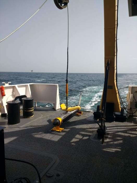


While this is happening, surveyors are also towing a MVP or Moving Vessel Profiler to capture information about the water column. This is important because multiple factors in the water column need to be corrected in order for accurate sonar calculations. For example, the speed of sound in salt water is roughly 1500 m/s but may change while the ship is traveling over different parts of the sea floor or passing through a thermocline (steep temperature gradient) or halocline (steep salinity gradient). The MVP is similar to the CTD used on the launch boat (see previous post), but the MVP allows the ship to continue moving at about 10 knots (average survey speed), while the CTD must be cast when the ship is stationary.

For more information on multispectral analysis and sonar, see these resources:
https://oceanexplorer.noaa.gov/explorations/09bermuda/background/multibeam/multibeam.html
https://oceanservice.noaa.gov/education/seafloor-mapping/how_sidescansonar.html
Personal Log
One of my goals in the classroom is to teach students to be comfortable making and learning from mistakes. Making mistakes in math and science is common and welcome because they lead to great discussion and future change. Often, my sixth graders get discouraged or so caught up in failure that they become paralyzed in making further attempts. While aboard the Thomas Jefferson, I have witnessed several aspects not go according to plan. I think these experiences are important to share because they provide real-life examples of professionals coming together, learning from mistakes, and moving forward.
Around 4:00 am, the towfish side scan sonar became entangled with the MVP. This was a horrendous disaster. The crew spent about 16 hours contemplating the issue and collecting data using the multibeam only, which is less than ideal. One of XO LCDR McGovern’s many roles aboard the ship is to serve as the investigator. She reviewed tapes of the early morning, talked with the crew, and later held a debrief with all involved. When something like this happens, the ship must write a clear incident report to send to shore. There were many questions about why and how this happened as well how to best proceed. In the end, the towfish and MVP were untangled with no damage present to the sensor. Within the same day, both were cast out and back in use.
I find this to be an astounding example of perseverance and teamwork. Despite being disappointed and upset that a critical tool for collecting accurate data was in dire shape, the crew came up with a plan of action and executed. Part of the engineering and scientific processes include evaluation and redesign. Elements of the sea and a center drift of the side scan lead to a documented new plan and refiguring the process so that this is unlikely to happen again.


Peaks
+Saw a tuna eat a flying fish

+There is a large sense of purpose on the ship. Despite complex sleep schedules to enable 24 hour operations with a smaller crew, people are generally happy and working hard.
+ There seems to be an unlimited supply of ice cream in the ice cream freezer. Junior Officer, ENS Garrison Grant introduced me to a new desert- vanilla ice cream, a scoop of crunchy peanut butter, and chocolate syrup. I also found the rainbow sprinkles.
Thank you for sharing all the data, especially how the sonar works. And I have no doubt that you sprinkled those sprinkles !!