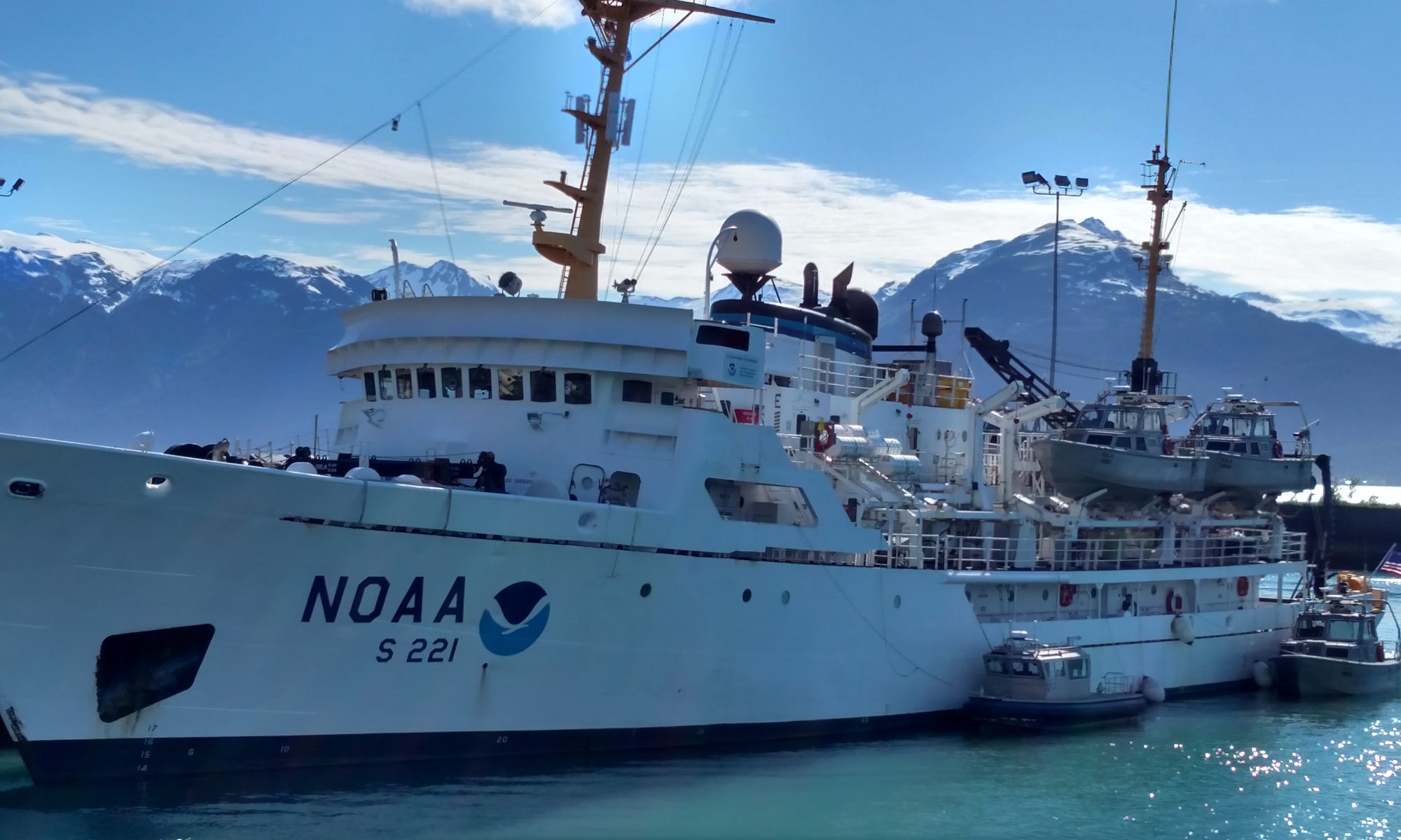
Sena Norton, July 11, 2004

NOAA Teacher at Sea
Sena Norton
Onboard NOAA Ship Rainier

July 6 – 15, 2004

Mission: Hydrographic Survey
Geographical Area:
Eastern Aleutian Islands, Alaska
Date:
July 11, 2004

Location: At anchor Popof Strait, Shumagin Islands, AK
Latitude: 55 deg 17.30’ N
Longitude: 160 deg 32.14’ W
Visibility: 5 nm

15:00

Direction: 110 deg
Wind Speed: 10 kts
Sea wave height: 0-1 ft
Swell wave height: n/a
Seawater temperature: 10.0 deg C
Sea level pressure: 1018.2 mb
Cloud Cover: 5/8
Weather: Fair to Partly cloudy, spots of fog dissipating. 12.12 deg C

Plan of the Day:
Continue the launch survey with 2 boats. In house data cleaning and processing. Meeting with LIDAR tech stationed in Sandpoint.

Science and Technology Log

I personally spoke with a survey technician, Amanda McKinney on board to gather more information on hydrography and the process behind it. There were two main topics that we discussed: Application and history of marine survey, and the math/science behind the techniques.

Application/History

The technology used for marine survey has been improving by leaps and bounds and we are currently using a collection of old and new technology to gather data. Many nautical charts have not been charted for almost 80 years or more and some areas have never been accurately charted at all. The old process was to drag a lead line behind a transiting ship. This process was full of errors because you could never accurately know your depth, even if the length of the line was known; it was drug and therefore skewed the data. Very often a charted depth from these old processes are found to be dangerous wrong. Another mode of survey is the wire drag, where multiple ships drag a wire through the water column. Once a target has been hit, the depth of that underwater target is calculated, but never truly charted accurately. Side scan sonar came around and improved the survey capability, but it too has its drawbacks. Because the “fish” is towed there are many more mathematical corrections that must be made in order to get a reading that is close to the actual target. It does produce wonderfully clear pictures of what is around the “fish” but those images lack depth of field and the sonar cannot read directly below the transmitter. Quite often with side scan images, divers are needed to dive the sight of a possible target to get accurate readings. Multi-beam sonar can be used in conjunction with side scan to better improve the over all picture of the underwater area. Because multi-beam is able to give more accurate readings and the data is complied in 3-D images, surveyors can have both a clear image and precise depth reading all together. It is hoped in the future that there will be new sonar systems that can scan at 480 beams over .25 x .25 deg per beam with 40+ pings per second. The highest level of technology currently used by NOAA is the Reson 8125 (this system is attached to two boats currently) and it sends out 240 beams over 0.5 x 1 deg / beam at 15 pings per second and runs with 455kHz. Remember, that a short pulse (wavelength) will give better vertical resolution and higher frequencies give shorter pulses or wavelengths.

The math required to figure the depth is not very difficult, however in the case of the ocean, the computers must adjust all readings for depth, salinity, temperature and density, which in a way makes the math more difficult if done by hand.

Depth=Speed+ Time/2

Personal Log

I was able to spend some time with the survey tech’s today and got through some of the PowerPoint presentations that are available here on the intranet to educate myself more on the technology and process. I was pleased to see that I can apply some of the simple ideas to my classroom. When I teach certain science skills I will have real life data sets and examples for the kids to analyze. I also hope to get some of the kids excited in the field of sonar and survey, much needs to be done to improve the accuracy and reliability of these systems and the product they produce.

Sunday equals fishing off the fantail in between shifts. We have a resident pack of gulls that have found it much to their benefit to hang out for the halibut leftovers that get tossed overboard or that slip from bait hooks.

I found a whale bone yesterday on Egg Island and had the boat shop guys saw it in half so that both of us TAS’s could bring something back for the classroom. It is not a large chunk, but authentic to say the least. I also gathered some sea sponge that had washed up and a very unique white rock.

I was very surprised to see the people working on a Sunday. No one should ever question the dedication of the folks on board or say that this is an easy job. One of the engineers has not had a day off in two months or more. The ship is something that has to be tended too by her crew and command 24 hours a day 7 days a week. Self-sufficiency comes with some responsibilities!

Question of the Day

Which is better: side scan or multi-beam sonar?

There is not one that is better than the other so much as they can compliment each other to produce and more detailed and accurate product, namely the nautical charts and other products that use the information gathered via the sonar medium.

Sena Norton, July 8, 2004

NOAA Teacher at Sea
Sena Norton
Onboard NOAA Ship Rainier

July 6 – 15, 2004

Mission: Hydrographic Survey
Geographical Area:
Eastern Aleutian Islands, Alaska
Date:
July 8, 2004

Location: Sonar Patch cruise, SE of Devils Bay on AK peninsula
Latitude: 55 46.163 N
Longitude: 158 03.557 W
Visibility: < 1 nm
Direction: 229 degrees
Wind Speed: 16 kt
Sea wave height: 1-2 ft
Swell wave height: 1.2 ft
Seawater temperature: 8.9 deg C
Sea level pressure: 1021.1 mb
Cloud Cover: n/a fog
Weather: Fair and foggy, 8.9 deg C dry / 9.4 deg C wet

Plan of Day: 1.5 days of sonar readings in patch with lines of 2.5 hours each. Launch #5 boat for survey north of ship around a possible rock pinnacle.

Science and Technology Log

Sonar Systems on board RAINIER: How they work.

What is Sonar?

In its most basic sonar are sound waves that are produced and then bounced back off of an object and recorded. Since the speed of sound is a known figure, the amount of time it takes for the sound wave to return to the transmitter/receiver gives a collectable image of that object. The deeper objects are the longer the sound wave takes to bounce back. Two types of sonar are single beam and multi-beam. Single beam is able to give high detail to an object but only shows a narrow swath, while multi-beam has a large footprint and can show a larger over all area. There are limits to the depth sonar can go because of the density of the water column. If the water is very dense the sound waves are slowed down and do not transmit the correct timing, therefore the image will be distorted. All images created must be analyzed after the density, temperature and salinity of the water column is taken into consideration.

Sonar is a very powerful sound wave and it can be dangerous, although it is at a frequency that humans or marine mammals cannot hear. If a diver were scanned they would be susceptible to a high-level concussive power. The emitter itself requires a large volume of power and if a human were to be near it during an emission it would do a great deal of damage. Think of the concussion from a bomb or firework, sonar is many, many more times as powerful.

RAINIER’s Sonar:

The ship is equipped with a deep sonar transmitter; it is attached to the hull and is used for scanning deep water where resolution is not a large issue. The boat “mows the lawn” in a patch of ocean. Each pass is numbered and the data collected. The lines are about 2 hours at 7-8 knots long. For more detailed work or a smaller area the ship will use one of its 6 launches that are also equipped with various sonar transmitters. These small boats will conduct and similar pattern of lines and collect the data right on board. The data is then transferred to the computers on board to go through technician cleaning and final analysis.

Sonar Types:
Single-beam – one beam sent and received.

Multi-beam – up to 240 beams per 180 degrees sent and received. As depth increases the foot print widens.

Analysis of data:

When the soundings are collected they are run through a Carris computer program where the technicians can manually scan each line. There are techs assigned to each “sheet” or area. Each line is cleaned, meaning outliers are removed or other “noise” is deleted. Once the data is clean a complete 3-D image of the patch can be looked at with all the data points represented. Once an entire area has been scanned objects become very clear, as if you were looking at them. From outlines of sunken ships from the side to large monolithic rocks protruding from the ocean floor, the detail and accuracy of the image is amazing. Once there is enough data the sounds can be turned into color-coded overlays that fit right on top of the fathom charts, so as to give a 3-D view of what those fathom readings represent. Red and orange or shallow and the colors move through yellow, green and finally blues, which are the deepest readings. Mountain ridges, lava floes, old wrecks, valleys and monoliths all come to life on the chart.

Personal Log

Steve Foye gave me a quick training with another new member of the crew on the job of Lookout on the flying bridge last night. He reviewed the 32-point compass and the difference between saying North relative to the ship verses trying to figure out the “real” compass coordinate. He explained you could use directions (NW or SE) or give the coordinates (90 or 270). Dead ahead would be 000, north relative to the ship or 360, all are correct for locating something directly off the bow of the ship.

Question of the Day:

When is the ship required to sound foghorn and place lookouts on the Bow/Flying Bridge?

When the visibility gets below 1 nm the ship is required to blow the foghorn or ring a bell every 2 minutes. A lookout is placed on the flying bridge during hours of darkness or low visibility. They move to the bow when the foghorn is turned on so they do not damage their ears.

Leyf Peirce, July 7, 2004

NOAA Teacher at Sea
Leyf Peirce
Onboard NOAA Ship Rainier

July 6 – 15, 2004

Mission: Hydrographic Survey
Geographical Area:
Eastern Aleutian Islands, Alaska
Date:
July 7, 2004

Time: 10:15
Latitude: N 57°31.730
Longitude: W 154°58.325
Visibility: 10 + m
Wind direction: 250
Wind speed: 18 knots
Sea wave height: 2 – 3 feet
Swell wave height: 2 – 4 feet
Sea water temperature: 10.6 °C
Sea level pressure: 1020.1 mb
Air temperature: 12.2 °C
Cloud cover: 2/8

Science and Technology Log

I talked more with P.S. Shyla Allen about how the multibeam echo sounders work on the ship to gather data about the depths of the ocean. Both the RAINIER and the launch ships use the following method to gather data. All of these vessels use echo sounders with anywhere from 120 to 240 beams that scan the ocean floor. The following diagram illustrates how this is done:

Peirce 7-7-04 Fig1
Figure 1: Multibeam Echo Sounding

Here, “z” is an echo sounding two-way travel time beam, and the multibeams are spread over the footprint distance of “f”. The size of the sound footprint, “f”, depends on the depth at which the measurement is taken, “z”. The greater the depth is, the greater the footprint is. However, the greater the footprint is also means less accuracy on the outer edges of the footprint. Therefore, the ship will run a “mowing the lawn” pattern across the given section to get desired overlapping of data:

Peirce 7-7-04 Fig2
Figure 2: Mowing the Lawn pattern

The width of these lines is determined by: width of x = 3 * z. By using this rough equation, the ship will be able to overlap the areas of least accuracy, i.e. the areas on the outer range of the footprint:

Figure 3: Ship running mowing the lawn pattern so the footprints overlap.

From this data, the depth and contours of the ocean floor can be determined. I also asked P.S. Shyla Allen about the problems and sources of error associated with this data collection. She responded by detailing three main issues that must be corrected when cleaning the data, i.e. the data must undergo three main correction factors before accurate readings can be analyzed. These three factors include: a) tide changes, b) sound velocity, c) the motion of the ship and GPS positioning. To correct for tide changes, the researchers must have accurate readings of the tides. Tide gauges are installed along the coastline at various points, and all readings are reduced to Mean Lower Low Water (MLLW). This basically gives the average of the lowest possible depth at a given location. To correct for sound velocity changes, which is the most important correction factor dealt with, researchers take measurements of water temperature and salinity level at the given depth reading. For every change of 1 ppm in salinity, there is a change of 3 m/s in sound velocity. Therefore, salinity is perhaps one of the most important factors. Finally, the motion of the ship and GPS position need to be corrected for. This includes correcting for the pitch, roll, and gyration of the ship as well as error in the GPS system. Because the ship uses Differential GPS (DGPS), this error is already accounted for. However, for the pitch, roll, and gyration of the ship, two antennas are used to on the port and starboard sides. These antennas, often referred to as Motion Reference Units (MRU), are very stable feed into the same computers that process the data. Therefore, the computer takes into account the readings from these antennas and combines this information with the corrections made for the tidal changes, sound velocity factors, and positioning of the ship. After cleaning the static from the data, a nautical chart can be produced. This method of charting the ocean floor is definitely more efficient than when researchers used lead lines—long ropes with lead that would be dropped down and then measured to determine the depth!

Personal Log

I woke up this morning after sleeping for about 12 hours—I think the seasickness medicine I took last night made me very sleepy. Luckily, however, all traces of seasickness are gone; I can even sit here at the computer and type without noticing the pitching of the ship very much at all. I think all of my muscles must be getting stronger as a result of reacting to the changing ground and all of the stairs I go up and down every day. I spent some time on the bridge this morning mostly asking questions about the tools used there and what various measurements mean. I find it very interesting that simply reading tiny numbers and using small switches and knobs will run this 231 foot ship. However, my experience aboard ships tells me that it is not even close to impossible. I know that even the slightest adjustment at the helm on a sailboat can change the course of the boat. I am reminded of sailing in the British Virgin Islands and the dispute over if it was more important to maintain the way point or try to make the boat go very fast. However, that is not an issue on this boat. We are supposed to reach the Shumagin Islands tonight, and tomorrow we will start the launches—I can’t wait!

Question for the Day

How many sets of data points must be filtered out before the data is considered clean? On what does this number depend? How does one determine if a data point is an outlier or and actual reading?