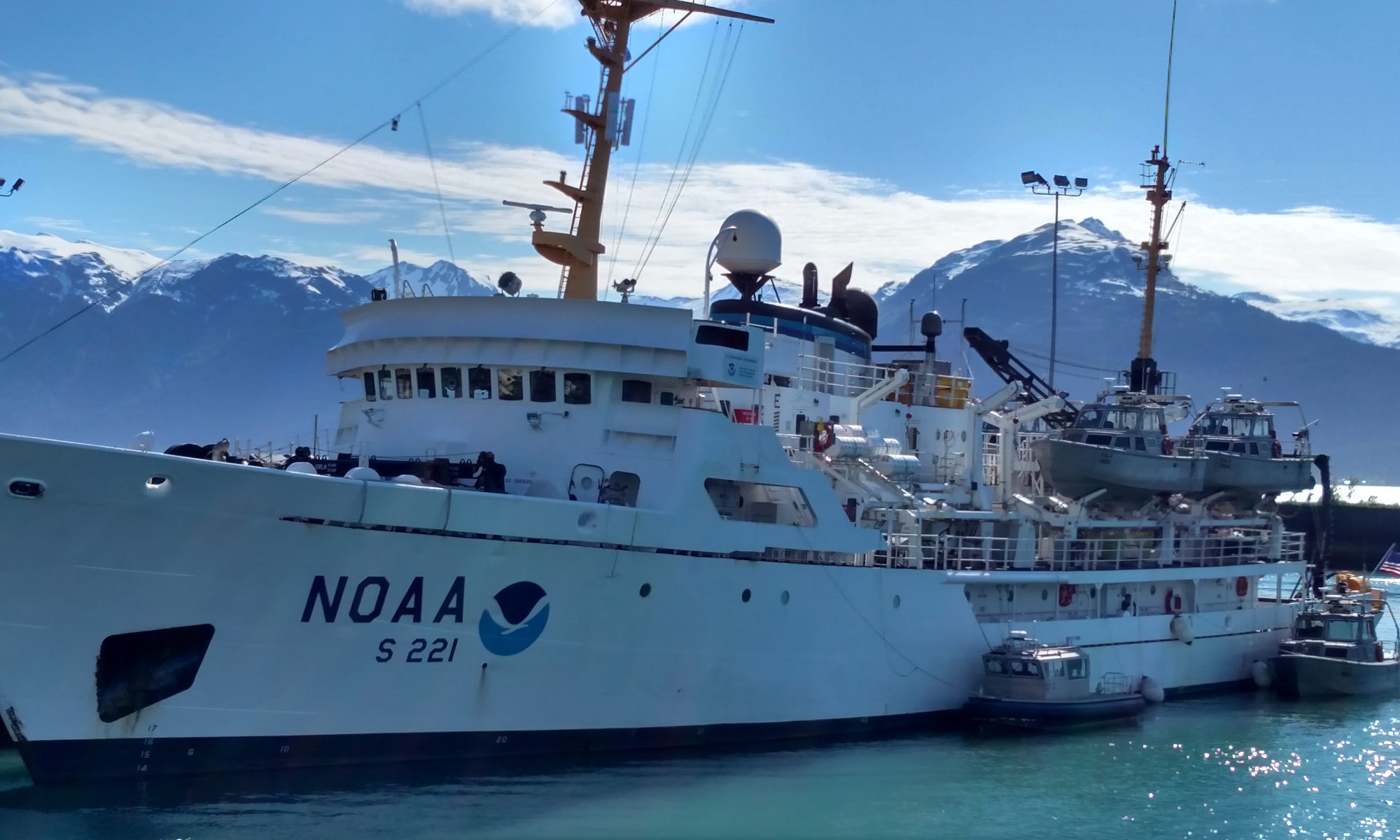
Geographic area of the cruise: Atlantic Ocean, off the coast of North Carolina and South Carolina
Date: July 28, 2014
Weather Information from the Bridge
Air Temperature: 27.5 C
Relative Humidity: 86%
Wind Speed: 15.03 knots
Science and Technology Log
There is a lot of work that goes into allowing the fishery team to be able to set traps every day. The acoustics lab/ night shift is responsible for creating the maps of the seafloor that will be used the following day. The team consists of David Berrane a NOAA fisheries biologist, Erik Ebert a NOAA research technician, Dawn Glasgow from the South Carolina Department of Natural Resources and a Ph.D student at the University of South Carolina, as well as Mary a college student studying Geology at the College of Charleston and Chrissy a masters student at the University of South Carolina. This team is amazing! Starting at around 5:00 pm the day before they stay up all night mapping the ocean floor.
The night shift collecting data
Every night Zeb Schobernd lets the night shift know which boxes they will work on. These boxes are created in the offseason by the research scientists, they base their selection on information from fishermen, the proximity to already mapped areas, weather and previous experiences. The first step in creating a bathymetric map is to create a line plan, which lets the ship know which area will be covered. The average line takes about half an hour to complete but they can take up to several hours. The ship drives along these lines all night long while the team uses the information that is gathered to create their maps.
So how do they get this information? The ship uses sonar to collect data on the water column and the ocean floor. The Pisces has a 26 multi-beams sonar system, which allows the research team to create a better picture, compared to using single beam sonar. The beams width is about 3 times the depth of water column. This means that depending on how deep the water is in any given location, it will determine how many lines need to be run to cover the area.
Multi-beam sonar (picture from NOAA)
The picture below is one of the computer screens that the scientists look at throughout the night. It provides the sonar information that will then be used to map the floor. Sonar works by putting a known amount of sound into the water and measuring the intensity of the return. A rock bottom will yield a stronger return while a sand bottom will absorb the sound and yield a less intense return. In the image red means that there is a more intense return while blue and yellow signifies a less intense return. You will notice in the center screen there is a strong red return at the top of the beam this is because the ship is sending out the sound and it takes about four meters until you start recording information from the sea floor.
SIMRAD (multi-beam sonar)
Finally before the maps can be created the team has to launch an XBT (expendable bathy thermograph) two times per box or every four hours. The XBT measures the temperature and conductivity of the water, this is important because sound travels at different rates in cold versus warm water. This information is then used when the scientists calculate the sound velocity, which is used to estimate the absorption coefficient of sound traveling through the water column.
Once the data is collected the team begins the editing process. First they have to remove random erroneous soundings in order to get an accurate map; they fondly call this process dot killing (this basically means getting rid of outliers). They do this by drawing a box around the points of data they want to remove and deleting the point. Next they apply tide data to account for the deviations in the tides, this information is obtained from NOAA and is based on the predicted tides for the area. Finally they apply the sound absorption coefficient.
Editing the data (killing dots)
The final product is put into GIS (Geographic Information Systems), which the chief scientists will use to determine where the traps should be set the following morning. On the map below blue indicates the deepest areas while red shows the shallowest. The scientists want to place the traps in areas where there is a large change in depths because this is usually where you will find hard bottoms and good fish habitats.
Finished map
Personal Log
I have spent the past three nights in the Acoustics/Computer Lab with the night shift mapping the ocean floor. While the ship sails along the plotted course, I have had the opportunity to see the sunrise and sunset on the Pisces as well as a lightning storm from the top deck.
Lighting on the ocean (picture from sciencedaily)
On Thursday night a little after midnight after launching the XBT we see decided to go onto the top deck of the Pisces to get a better look at the lighting storm in the distance. Even at night it was still humid and hot and as we climbed up to the top deck it was dark all around us until suddenly there would be a flash of color in the clouds and you could see everything, until it went dark again. We tried to take a picture but the lightening was just too fast for our cameras. This is the closest picture I could find to what it was like that night except the water was not calm.
SPOTLIGHT ON SCIENCE
Name: Erik Ebert Title: Research Technician
Erik editing data collected on Sunday July 26th.
Education: Cape Fear Tech (Wilmington, NC)
How long have you worked for NOAA/NOS: 6th field season, 5th year
Job Summary: I work on ecosystem assessments throughout the Gulf of Mexico South Atlantic & Caribbean
– Team oriented production of ocean floor maps
– System setup & keeping the acoustic systems operating correctly
How long have you participated in this survey: Since 2010
What do you like about your job: That the data we collect, and the maps we create can be used again for different studies. The types of data we collect includes bathymetric data, information on the water column, & fish that populate the water column.
How many days are you at sea: 60 days (April-November)
What do you do when you are not on the boat: Process & produce fish density maps from the data collected during the cruises. I also work for National Ocean Services (provide data to policy & decision makers to the state of the ecosystem)
Most challenging about research on a ship: Being away from home is the biggest challenge.
What would be your ideal research cruise: My ideal research cruise would be a cruise similar to what we just completed in Flower Garden Banks in the Gulf of Mexico. It was a 3-year assessment of the reef ecosystem using ROV, Diving and Acoustics to study how the ecosystem changed over time.
Favorite fish: Trigger Fish “cool swimming behavior”
The last couple of days have been the best ever: beautiful weather, hard work, deep science. We acquired data along the continental shelf and found a cool sea floor canyon and then set benchmarks and tidal gauges.
In hydrography, we gather data in seven steps, by determining: our position on Earth, depth of water, sound speed, tides, attitude (what the boat is doing), imagery and features. Step 1 is to determine where we are.
In this picture you can see a GOES satellite antenna (square white one) that is used to transmit tide data ashore and a GPS antenna (the small white eggs shaped one) that provides the tide gauge with both position and UTC time. Photo by Barry JacksonIn this picture Brandy Geiger, Senior Survey Technician, uses GPS to record the positions of the benchmarks we have just set for the tide gauge. Photo by Barry JacksonWhere we are happens to be the most beautiful place on earth. Photo by Barry Jackson
In Step 2, we determine the depth of the water below us.
Bathymetry is a cool word that means the study of how deep the water is. Think “bath” water and metry “measure.” When your mom tells you to get out of the tub, tell her to wait because you’re doing bathymetry.
As I explained in my first blog, we measure depth by sending out a swath of sound, or “pings,” and count how long it takes for the pings to return to the sonar, which sits beneath the ship or smaller boat.
Yesterday we used the multi-beam sonar to scan the sea floor. Here is a screen shot of the data we collected. It looks like a deep canyon, because it is!
Here is the image of the sea floor canyon Starla Robinson, a Senior Survey Technician, and I discovered. We decided it should be named Denla Canyon, after the two scientists who discovered it.
Here I am, gathering pings.
While collecting data, I kept in contact with “the bridge,” the team responsible for navigating the ship, by radio to ensure the ship’s safety and maximum, quality data acquisition. Photo by Starla Robinson
Step 3, we take into consideration the tide’s effect on the depth of the water. Tides are one predictable influence on water depth. There are over 38 factors or “constituents” that influence the tides. The gravitational pull of the sun and the moon at various times of the day, the tilt of the earth, the topography, and many other factors cause water to predictably bulge in different places on earth at different times. The Rainier crew works 24 hours a day and 7 days a week, so they must find a way to measure depth throughout the days and month, by taking into account the tide. Arthur Doodson, who was profoundly deaf, invented the Doodson Numbers a system taking into account the factors influencing tide in 1921. Flash forward to the 21st century, our Commanding Officer, Commander Rick Brennan worked with a team of NOAA scientists to develop a software program called TCARI, as an alternate method to do tide adjustments, taking into account 38 factors, even the moon’s wobble. Inventions abound at NOAA.
The Rainier crew worked for 14 hours today to set up a tide gauge station, an in depth study of how the tide affects our survey area. On this map, there is a Red X for each tide gauge we will install. This process only happens at the beginning of the season, and I feel fortunate to have been here–the work we did was….amazing.
Each Red X is approximately where a tide gauge will be installed. The one we installed today in Driver Bay is in the north west corner of the sheet map.
You can see an animation here that shows the combined effect of two sine waves that produce a signal like our tide data. Just imagine what it looks like when you factor in 38 different variables.
The earth goes around the sun in 24 hours and moon goes around the earth in a little more than 12 hours, much like these two gray sine waves. Interestingly, when you add two different waves, you get the wonky blue sine wave, with ups and downs. This combined effect of the sun and the moon (two dots) causes the ups and downs of the tide (blue wave). Graph taken from Russell, D. Acoustics and Vibration Animation, PSU, http://www.acs.psu.edu/drussell/demos/superposition/superposition.html.
Low tide is the best time to see sea stars, mussels and barnacles, but it is also a more hazardous time in the tidal cycle for mariners to travel. Therefore, navigational charts use the mean lower low water level, low tide, for the soundings, or depth measurements on a chart. The black numbers seen on a nautical chart, or soundings, represent depth measurements relative to mean lower low tide. Driver Bay, the area on the chart where we installed the tide gauge today, is the crescent shaped bay at the northwest end of Raspberry Island.
This is a nautical chart used to help mariners navigate safely.
Installing Tide Gauge Stations
Before gathering sonar data, ground and boat crews install a tide gauge to measure changes in water level and to determine the mean lower low water level datum. A tide gauge is a neat device that has air pumped into it, and uses air pressure, to determine how deep the water is. The tide gauge uses a formula of (density of sea water)(gravity)(height) = pressure. The gauge measures pressure, and we apply factors for gravity and sea water. The only missing factor is height, which is what we learn as the gauge collects data. This formula and nuances for particular locations is a fascinating topic for a blog or master’s thesis. Scientists are looking for tidal fluctuations and other location specific variances. Then, by computer they determine the mean lower low tide depth, factoring in the tidal fluctuations.
There are permanent tide gauge stations all over the world. The nearest permanent tide gauge station to our study area is in Kodiak and Seldovia. These permanent gauges take into account many factors that affect tides over a 19 year period of time, not just the gravitational pull of the moon.
The tide gauge stays in place for at least 28 days (one full tidal cycle). During the month, data of the tides is collected and can be compared to the other tide gauges we install.
Installing the Tide Gauges and Benchmarks
Excitement built as the crew prepared for the “Tide Party,” packing suitcases full of gear and readying the launches. Installing Tide Gauges signals the beginning of the season and is one of the few times crew gets paid to go on shore.
Why Bench Mark?
There are three reasons I have figured out after many discussions with patient NOAA crew as to why we put in bench marks.
I installed this benchmark in Driver Cove by having a hole drilled in bedrock and affixing the benchmark with concrete if anyone ever returns and needs to know their exact location. Photo by Barry Jackson
The first reason we install benchmarks is to provide a reference framework to ensure both our tide staff and the tide gauge orifice are stable and not moving relative to land. The second reason is if we ever come back here again to gather or compare data to previous years, we will know the elevation of the tidal datum at this location relative to these benchmarks and can easily install a new tide gauge. The third reason is that the earth and ocean floor changes constantly. As scientists, we need to make sure the survey area is “geologically stable.” We acquire several hours of GPS measurements on the primary benchmark to measure both its horizontal and vertical position relative to the earth’s reference frame. Should there ever be an earthquake here, we can come back afterwards and measure that benchmark again and see how much the position of the Earth’s crust has changed. After the last big earthquake in Alaska, benchmarks were found to move in excess of a meter in some locations!
Teacher on Land Polishing Her Benchmark Photo by Brandy Geiger
Installing the Benchmark
Today, our beach party broke into two groups. We located stable places, at about 200 foot intervals along the coastline. We drilled 5 holes on land and filled them with concrete. A benchmark is a permanent marker you may have seen at landmarks such as a mountain peak or jetty that will remain in place for 100 years or more. We stamped the benchmark by hand with a hammer and letter stamps with our station identification. If we chose a good stable spot, the benchmark should remain in the same location as it is now.
Tide Gauge
As one group sets up benchmarks, another group installed the tide gauge.
Here, Chief Jim Jacobson, Lead Survey Technician, sets up a staff, or meter stick, I used to measure the change in water depth and others used for leveling. Photo by Barry Jackson
To install the tide gauge, you must have at least three approved divers who install the sensor in deep water so that it is always covered by water. Because there were only two crew on board trained to dive, Lieutenant Bart Buesseler, who is a dive master, was called in to assist the team. The dive team secured a sensor below the water. The sensor measures the water depth with an air pressure valve for at least 28 days. During this time there is a pump on shore that keeps the tube to the orifice pressurized and a pressure sensor in the gauge that records the pressure. The pressure is equal to the number of feet of sea water vertically above the gauge’s orifice. An on-board data logger records this data and will transmit the data to shore through a satellite antenna.
Divers install the tide gauge, and spent most of the day in the cold Alaska waters. Good thing they were wearing dive suits! Photo by Barry Jackson
Leveling Run
After the gauge and benchmarks are in place, a group does a leveling run to measure the benchmark’s height relative to the staff or meter stick. One person reads the height difference between 5 different benchmarks and the gauge. Then they go back and measure the height difference a second time to “close” the deal. They will do the same measurements again at the end of the survey in the fall to make sure the survey area has not changed geographically more than ½ a millimeter in height! Putting the bubble in the middle of the circle and holding it steady, leveling, was a highlight of my day.
Observation
Finally, a person–me– watches the staff (big meter stick above the sensor) and takes measurements of the water level with their eyes every six minutes for three hours. Meanwhile, the sensor, secured at the orifice to the ocean floor by divers, is also measuring the water level by pressure. The difference between these two numbers is used to determine how far below the water’s surface the orifice has been installed and to relate that distance to the benchmarks we have just leveled to. If the numbers are consistent, then we know we have reliable measurements. I won’t find out if they match until tomorrow, but hope they do. If they don’t match, I’ll have to go back to Driver Bay and try again.
As we finished up the observations, we had a very exciting sunset exit from Raspberry Island. I was sad to leave such a beautiful place, but glad to have the memories.
Last minute update: word just came back from my supervisor, Ensign J.C. Clark, that my tidal data matches the gauge’s tidal data, which he says is “proof of my awesomeness.” Anyone who can swim with a car battery in tow is pretty awesome in my book too.
The data Starla Robinson and I collected is represented by the red line and the data the gauge collected is represented by the blue line. The exact measurements we collected are on the table.
Spotlight on a Scientist
Lieutenant Bart Buesseler came to us straight from his family home in the Netherlands, and before that from his research vessel, Bay Hydro II. The main reason our CO asked him to leave his crew in Chesapeake Bay, Maryland, and join us on the Rainier is because he is a dive master, capable of installing our sensors under water, and gifted at training junior officers.
Lieutenant Beusseler knows he needs to be particularly nice to the amazing chefs aboard Rainier, including Floyd Pounds, who cooks food from every corner of our ocean planet with a hint of a southern accent.
During his few years of service, LTJG Buesseler adventured through the Panama Canal, along both coasts of North America, and has done everything from repairing gear to navigating the largest and smallest of NOAA vessels through very narrow straits. He loves the variety: “if I get tired of one task, I rotate on to another to keep engaged and keep my mind sharp.” He explains that on a ship, each person is trained to do most tasks. For example, he says, “during our fast rescue boat training today, Cal led several rotations. But what if he is gone? Everyone needs to be ready to help in a rescue.” Bart says at NOAA people educate each other, regardless of their assignments, “cultivating information” among themselves. Everyone is skilled at everything aboard Rainier.
In the end, he says that all the things the crew does are with an end goal of making a chart. His motto? Do what you love to do and that is what he’s doing.
Personal Log
Today was a special day for me for many reasons. It is majestic here: the stark Alaskan peninsula white against the changing color of the sky, Raspberry Island with its brown, golden, crimson and forest green vegetation, waterfalls and rocky outcroppings. I’m seeing whales, Puffins, Harlequin Ducks and got up close with the biggest red fox ever. Most importantly, I felt useful and simultaneously centered myself by doing tide observations, leveling and hiking. I almost dove through the surf to make it “home” to the ship just in time for a hot shower. Lieutenant Buesseler’s reference to “cultivating information” rings very true to me. In writing these blogs, there is virtually nothing I came up with independently. All that I have written is a product of the patient instruction of Rainier crew, especially Commander Brennan. Each day I feel more like I am a member of the NOAA crew here in Alaska.
I’ve donned an immersion suit, also known as a survival suit. One of the first things I did when I came aboard was to locate this suit and my life vest, two pieces of equipment that save lives. In the event we had to abandon ship, the survival suit would keep me both warm and afloat until rescue. During our evacuation drill we needed to unpack and get into the suit, and be completely zipped up in 60 seconds or less. Getting into the suit was much easier after I took my shoes off, as the soles caught on the fabric of the suit. The suit is made of neoprene, which was invented in 1930. SCUBA wetsuits are also made of neoprene, and even some laptop and tablet cases.
In an earlier blog I talked about the CTD being used to calibrate the sonar aboard the Oscar Dyson, but not all technologies on the Dyson are as high tech as the CTD and sonar equipment. In fact you can build a weather station at home that is similar to some of the equipment used by the Dyson’s crew. Below is a picture of a hygrometer. There are actually two hygrometers aboard, one is located on each side of the bridge. Hygrometers are used to measure relative humidity (how much moisture is in the air). Also pictured is the wind bird which shows the direction the wind is moving. The propeller was actually turning rapidly when the picture was taken. The camera was able to “stop” the action. The wind bird is mounted atop the jack staff, high above the bow.
Hygrometers are weather instruments used to measure relative humidity.
The following link shows you how to build six instruments for monitoring the weather.
If you checked out the above link, how many snow days to you think the kids in North Dakota had?
Did you check out ship tracker? If you did, the screen shot below will look familiar. The blue lines in the water display the Dyson’scourse. Each segment of the course is called a transect. Transects are numbered, enabling scientists to easily reference a location.
Oscar Dyson‘s course as of 6 18 13
Are you wondering why we have traveled in rectangular patterns? The scientists establish this course for a several reasons:
Transects run perpendicular to the coast line, covering a wide range of bathymetry over the shortest distance.
Regularly spaced transects (as opposed to randomly spaced or scattered) are correlated with historical data, and are the best way to describe the distribution of pollock.
The combination of transects collects sufficient data to allow scientists to estimate the overall size of the pollock population with a high degree of certainty.
Does anyone have an idea about the meaning of “bathymetry” and a “leg”? No, in this case a leg is not something you stand on. Bathymetry is the shape and depth of the ocean floor, and a bathymetry contour line on a chart connects points of equal depth (like a topographic map). A leg, in this context, is a segment of the overall distance covered in the survey.
The information collected during this year’s survey helps determine the number of pollock that can be caught in next year’s fishing season.
Here is the ship tracker link, you can check out the Dyson’s course and other NOAA ships as well.
I want to revisit the sonar of Mystery Mix One. In my last blog I talked about what was happening near the surface of the ocean. This time I want to focus beneath the sea floor.
Graphic provided by NOAA
Look beneath the red, yellow, and green bands, depicting the sea floor, at the blue color, notice how the density of color changes over time. The density of the color tells scientists about the composition of the sea bed. The denser the color, the denser or harder the seafloor is likely to be; probably, the places with the dark, dense color are rocky areas, which attract the fish schools seen in the water above.
Looking at this graph reminds me of an experiment that my husband worked on, when he worked for Charles Stark Draper Labs, in Boston, MA. He worked on a Gravity Gradiometer that was sent to the moon on Apollo 17. The gradiometer measured the changes in gravity. The changes in gravitational strength give scientists information about what lays beneath the moon surface, like the sonar provides information about the sea bed. The Gravity Gradiometer was a very specialized version of equipment that is commonly used in prospecting for oil on Earth. I am sharing this story because, in class, one of our foci is to take what we know and apply the knowledge to a new scenario. Next question: Where will what we know now, take us in the future?
Weather Data: Air Temperature: 21.0 (approx.70°F)
Wind Speed: 8.71 kts
Wind Direction: West
Surface Water Temperature: 22.99 °C (approx. 73°F)
Weather conditions: overcast
Science and Technology Log:
It’s day 13 aboard the Henry B. Bigelow and we have made the turn at our southern stations off the coast of North Carolina and are working our way back to port at some of our inshore stations off the coast of Maryland. You may wonder how each of the stations we sample at sea are chosen? The large area of Cape May to Cape Hatteras are broken into geographic zones that the computer will assign a set amount of stations to, marking them with geographic coordinates. The computer picks a set number of stations within each designated area so all the stations don’t end up all being within a mile of each other. Allowing the computer system to pick the points removes human bias and truly keeps the sampling random. The vessel enters the geographic coordinates of the stations into a chartplotting program in the computer, and uses GPS, the Global Positioning System to navigate to them. The GPS points are also logged on a nautical chart by the Captain and mate so that they have a paper as well as an electronic copy of everywhere the ship has been.
You may wonder, how does the captain and fishermen know what the bottom looks like when they get to a new point? How do they know its OK to deploy the net? Great question. The Henry B. Bigelow is outfitted with a multibeam sonar system that maps the ocean floor. Some of you reading this blog might remember talking about bathymetry this summer. This is exactly what the Bigelow is doing, looking at the ocean floor bathymetry. By sending out multiple pings the ship can accurately map an area 2.5-3 times as large as its depth. So if the ship is in 20 meters of water it can make an accurate map of a 60 meter swath beneath the boats track. The sonar works by knowing the speed of sound in water and the angle and time that the beam is received back to the pinger . There are a number of things that have to be corrected for as the boat is always in motion. As the ship moves through the water however, you can see the projection of the bathymetry on their screen below up in the wheelhouse. These images help the captain and the fisherman avoid any hazards that would cause the net or the ship any harm. A good comparison to the boats multibeam sonar, is a dolphins ability to use echolocation. Dolphins send their own “pings” or in this case “echos” and can tell the location and the size of the prey based on the angle and time delay of receiving them back. One of the main differences in this case is a dolphin has two ears that will receive and the boat just has one “receiver”. Instead of finding prey and sizing them like dolphins, the ship is using a similar strategy to survey what the bottom of the sea floor looks like!
Bathymetric data being collected by multibeam sonar technology on the BigelowBigelow multibeam sonar (NOAA)Echolocation schematic courtesy of the Smithsonian Institute
Personal Log:
The last few days I have been trying my hand at removing otoliths from different species of fish. The otoliths are the ear bones of the fish. Just like the corals we have been studying in Bermuda, they are made up of calcium carbonate crystals. They are located in the head of the bony fish that we are analyzing on the cruise. A fish uses these otoliths for their balance, detection of sound and their ability to orient in the water column.
If you remember, at BIOS, we talk a lot about the precipitation of calcium carbonate in corals and how this animal deposits bands of skeleton as they grow. This is similar in bony fish ear bones, as they grow, they lay down crystalized layers of calcium carbonate. Fisheries biologist use these patterns on the otolith to tell them about the age of the fish. This is similar to the way coral biologists age corals.
I have been lucky enough to meet and learn from scientists who work specifically with age and growth at the Northeast Fisheries Science Center Fishery Biology Program. They have been teaching about aging fish by their ear bones. These scientist use a microscope with reflected light to determine the age of the fish by looking at the whole bone or making slices of parts of the bone depending on what species it is. This data, along with lengths we have been recording, contribute to an age-length key. The key allows biologists to track year classes of the different species within a specific population of fish. These guys process over 90,000 otoliths a year! whew!
The information collected by this program is an important part of the equation because by knowing the year class biologists can understand the structure of the population for the stock assessment. The Fishery Biology program is able to send their aging and length data over to the Population Dynamics Branch where the data are used in modeling. The models, fed by the data from the otoliths and length data, help managers forecast what fisheries stocks will do. It is a manager’s job to the take these predictions and try to balance healthy fish stocks and the demands of both commercial and recreational fishing. These are predictive models, as no model can foresee some of the things that any given fish population might face any given year (ie food scarcity, disease etc.), but they are an effective tool in using the science to help aid managers in making informed decision on the status of different fish stocks. To learn more about aging fish please visit here.
Otoliths (fish ear bones) that I removed from a ButterfishYou can see here an otolith that is 1+ years old. It was caught in September and that big 1st band is its Year 0. You can see that the black dot demarks the fish turning 1. You can then see the Summer growth but not yet the winter growth. This fish has not yet turned 2, but it will be Jan 1st of the next year.
I have to end with a critter photo! This is a Cobia (Rachycentron canadum).
NOAA Teacher at Sea Marsha Skoczek Aboard NOAA Ship Pisces July 6-19, 2012
Mission: Marine Protected Areas Survey Geographic area of cruise: Subtropical North Atlantic, off the east coast of Georgia. Date: July 15, 2012
Location: Latitude: 32.47618N
Longitude: 78.19054 W
Weather Data from the Bridge Air Temperature: 27.6C (81.7 F)
Wind Speed: 6 knots (6.9 mph)
Wind Direction: From the SE
Relative Humidity: 75 %
Barometric Pressure: 1018.3
Surface Water Temperature: 28.4C (83.12 F)
Science and Technology Log
In order for the scientists to find the fish they are studying on this cruise, they need to know where the areas of favorable habitat are located. Old nautical charts are not one hundred percent accurate–sometimes they can be hundreds of kilometers off. Early ocean floor mapping used long lines with a lead weight which was hung off the side of the ship. As the ship moved forward through the water, the long lines would get behind the ship making it very difficult to get an exact reading. It wasn’t until sonar came into general use during World War II, that it was discovered to be useful for bathymetric mapping.
Sonar works by sending a single sound wave to the ocean floor. As it reflects back toward the ship, a hydrophone listens for the return sound. The length of time it takes for that sound wave to return to the ship can be used to calculate the depth of the ocean in that location. The speed of sound in water travels at approximately 1,500 meters per sec (m/s) which is about five times faster than sound travels in air. The problem with single beam sonar is that the data only plots the one single line beneath the ship. It does not give the complete picture and gaps in data were often filled in using the readings taken around the area as an estimate.
Planned acoustic survey lines
So how is multibeam sonar different from single beam sonar? With multibeam sonar, it is just as the name implies–multiple sound beams are sent toward the ocean bottom. For the depths we are working on, the multibeam sonar on the Pisces sends out 70 beams of sound every .67 seconds. Within a fraction of a second, these “pings” are reflected off of the ocean bottom and back to the transducer. The time it takes for all 70 of those pings to return to the transducer determines the depth at each point. The echogram screen illustrates the bottom features in real time and will even pick up large schools of fish in the water column. As the ship continues to move up and down the survey lines, the raw data is collected. The distance between the survey lines is determined by the depth of the area to be mapped. To set the survey lines, we are using 1.5 times depth so, if the water depth averages 100 meters at the mapping location, the survey lines are set at 150 meters, (.08 nautical miles) apart. Tonight, the ocean depth at our mapping location is about 60 m so the survey lines are set at 90 meters (.05 nm) apart. The goal when laying out the survey lines is to overlap the previous lines by about 25%. This will insure a more complete picture.
Echogram of ridge
It is not simple enough to just take the raw data from the return pings. The temperature, salinity and depth of the ocean in the mapping area can create slight variations in the return speed. Temperature, salinity and depth can influence the speed of the return signal, so we use the CTD to gather readings each morning as they are wrapping up the mapping for the night. This information along with the information on the ship’s roll, pitch, and yawl from the Position and Orientation System for Marine Vessels (POSMV) are plugged into software that helps process and clean up the data. From there, the data is converted into a “geo tif” file where it can be plugged into GIS mapping . The final product is a full color 3-dimensional image of the mapping area.
Completed multibeam image
Ideally the scientists would have multibeam information for each of the sites they want to study that day. To make this happen, the night before the ROV dive the ship will make its way to the next day’s study area so the geographers can map all night. The survey lines are selected using bathymetry maps as well as looking at the existing multibeam maps of the area to see if there are any gaps that need to be filled in. The idea is to give the scientists as much information as possible so they can make informed decisions about where to study. Time on the ship is extremely expensive and they want to make sure they take full advantage of that time by finding the best habitats to study. Without the multibeam images, the scientists have to make a best guess as to where to map using old and possibly out of date information.
Personal Log
This is the engine monitoring station.
Today I took a tour of the Pisces’ engine room. Engineer Steven Clement was nice enough to show me around and explain everything for me. It is amazing to me how this ship is like its own little city. The ship creates its own electricity using diesel-powered generators. It takes four generators to power the ship at full speed which is about 15 knots. The engines are so loud that I had on double ear protection and it was still extremely loud to walk past them. Using all four engines all day would burn up 3,000 gallons of diesel fuel. The Pisces is capable of holding 100,000 gallons of fuel which should last the ship several months at sea. The electricity that is left over from powering the engines is used as the power supply for all of the electronics on board.
Other ways that the Pisces reminds me of a small city is the water. The ship creates its own drinking water with a reverse osmosis system complete with UV filter and is capable of producing 2.8 gallons per minute. It also has two hot water heaters attached to a compressor to keep the hot water pumped up into the pipes of the ship. I do have to say that the hot water on this ship is extremely hot!! There is no need to wait for hot water, it comes out instantly when I turn on the faucet. When I shower, I have the cold on full blast and just a smidge of hot water to get a normal temperature shower. Even our waste water is cleaned up in the Pisces’ own waste water treatment facility which uses microbes to break down the waste products before it is released back out to sea.
Other than pulling into port occasionally for fuel and supplies, the Pisces is really a self-contained vessel capable of cruising at sea for long periods of time.
Ocean Careers Interview
In this section, I will be interviewing scientists and crew members to give my students ideas for careers they may find interesting and might want to pursue someday. Today I interviewed Dr. Laura Kracker.
Dr. Laura Kracker
What is your job title? I am a Geographer with NOAA National Ocean Service in Charleston, South Carolina.
What type of responsibilities do you have with this job? Usually I work on projects using acoustics to map fish in the water column. Using fisheries acoustics, we can map the distribution of fish in an area and detect large schools as well. On this mission, I am using multibeam to map seafloor habitats.
What type of education did you need to get this job? I earned my Associate’s Degree in agriculture from Alfred College in New York. When my children were little, I stayed home with them. While I was home with them I earned my Bachelors in Painting. Then I went to work in a fisheries office for a couple of years before deciding to go back to college to get my Master’s Degree in Interdisciplinary Science from the University of Buffalo. I then continued on to my PhD in Geography and GIS, also from the University of Buffalo. My dissertation was on Using GIS to Apply Landscape Ecology to Fish Habitats. So I have combined all of my experiences to get me to where I am today.
What are some of your best experiences have you had with this job? I love being on a ship. I spend as many as 55 days a year on ships, often at the request of other scientists that need help with multibeam sonar. I love geography, it gives us a framework to put everything together, you can layer more and more information onto a map to find a complete picture.
What advice do you have for students wanting a career in marine biology? Get a broad foundation before you specialize. You don’t have to take a direct route to where you want to go.