
NOAA Teacher at Sea
Christy Garvin
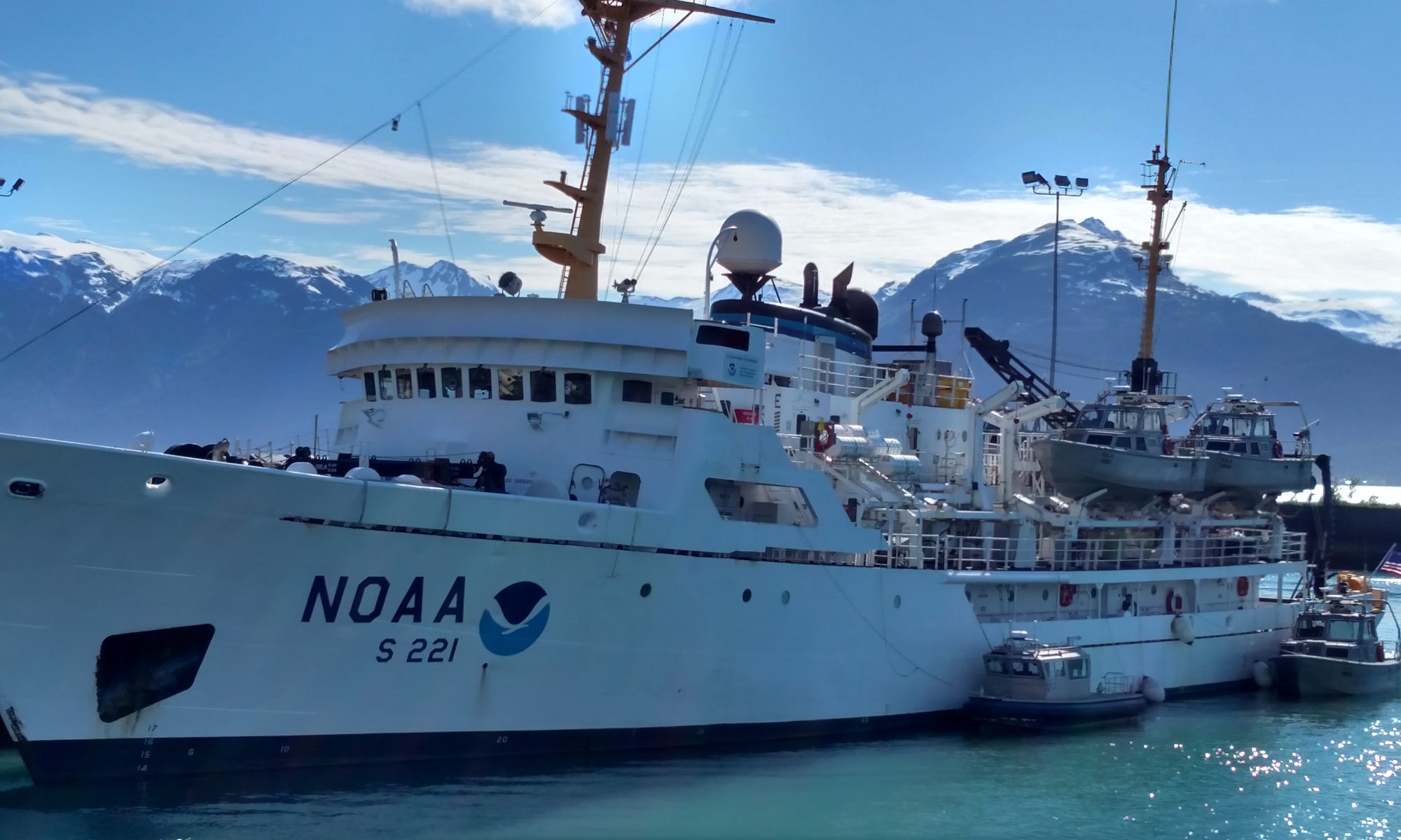
Onboard NOAA Ship Rainier
June 1 – 8, 2005
Mission: Hydrographic Survey
Geographical Area: Aleutian Islands, AK
Date: June 6, 2005
Weather from the Bridge
Latitude:56 deg 59 min N
Longitude: 135 deg 17 min W
Visibility: 11 nautical miles
Wind Direction: 290 deg
Wind Speed: 10 kts
Sea Wave Height: 0-1 ft
Swell Wave Height: 0 ft (we are in a protected bay)
Sea Water Temperature: 50deg F
Sea Level Pressure: 1011.7 mb
Science and Technology Log
My assignment today was to work on launch RA-2 taking bottom samples and running “holiday lines.” A holiday line is an area where previously drawn survey lines did not provide 100% coverage of the ocean floor, in other words, a small hole in the data. Our launch was working on sheet R in Leesoffskaia Bay and Aleutkina Bay. These bays are near Emengton, Long, and Baranoff Islands. Taking bottom samples is a very simple but important task. The information gathered allows boaters to know where good anchorage locations are and fishermen to figure out probable fish habitats and increase their yield.
In order to take a bottom sample, survey techs pre-select specific locations to be sampled. Once in the launch, the target is selected on the computer, and the coxswain drives to that location. The survey tech then takes a depth sounding to record the exact location and depth where the bottom sample is being taken. A device called a clam is attached to a rope and thrown overboard; when the clam hits the bottom a spring releases causing the “mouth” to shut and capture sediments on the ocean floor. The clam is then pulled to the surface and opened so that the survey tech can record the type of sediment or rock present. Later, this data is added to nautical charts as an aid to boaters.
Personal Log
Last night the crew of the RAINIER had a nice beach party. A nearby island was chosen, and crewmembers were ferried over to stretch their legs, hike around the island, and enjoy a bonfire. It was a nice surprise to end the weekend.


