NOAA Teacher at Sea Wes Struble Aboard NOAA Ship Ronald H. Brown February 15 – March 5, 2012
Mission: Western Boundary Time Series Geographical Area: Sub-Tropical Atlantic, off the Coast of the Bahamas Date: March 4, 2012
Weather Data from the Bridge
Position:30 deg 37 min North Latitude & 79 deg 29 min West Longitude
Windspeed: 30 knots
Wind Direction: North
Air Temperature: 14.1 deg C / 57.4 deg F
Water Temperature: 25.6 deg C / 78.4 deg F
Atm Pressure: 1007.2 mb
Water Depth:740 meters / 2428 feet
Cloud Cover: 85%
Cloud Type: Cumulonimbus and Stratus
Science/Technology Log:
In the previous log I described a CTD cast in detail from start to finish. Now that the CTD platform is on the deck of the Ron Brown the actual sampling process can begin. The CTD has a number of Niskin bottles holding a little more than 10 liters of water each. Water samples from each bottle must be collected and analyzed for various parameters which could include: Salinity, Oxygen content, Inorganic carbon, and others. On this cruise most of the CTD casts were sampled for both salinity and dissolved oxygen.
The first step in measuring salinity involves a careful rinsing of the sample bottles. After a standard three rinses, the bottle is filled and the depth from which the water was sampled is recorded for each bottle.
As a beautiful western Atlantic sunset falls on the Ron Brown another night of CTD's beginsI prepare a water sample for dissolved oxygen analysis after a CTD Cast at 2:00 amThe dissolved oxygen analysis lab station in one of the science labs on the Ron Brown
The full sample bottles are then either taken to the dissolved oxygen lab station or the Salinity lab station for analysis.
A close-up of the amperometric titration apparatus for analysis of dissolved oxygen in one of the science labs on the Ron Brown. A solution of Manganese Chloride and a combination of Sodium Hydroxide/Sodium Iodide is added to the water sample to sequester the oxygen and then when the temperature is stable the solution is amperometrically titrated with thiosulfate.The Ron Brown off the starboard stern from the workboatThe "climate airlock" leading to the salinity analysis lab. The airlock helps keep the water samples under constant temperature and humidity conditions.The two Autosals in the Salinity lab. These are precision instruments for measuring the salinity of seawaterA east-west cross-section across the eastern Atlantic Ocean. The eastern US coast is at left. The diagram illustrates north (reds)-south (blues) movement of the Antilles and Deep Western Boundary Current. Vertical scale in meters horizontal scale in 100,000 meter units (100 kilometers)
NOAA Teacher at Sea Wes Struble Aboard NOAA Ship Ronald H. Brown February 15 – March 5, 2012
Mission: Western Boundary Time Series Geographical Area: Sub-Tropical Atlantic, off the Coast of the Bahamas Date: March 2, 2012
Weather Data from the Bridge
Position: 26 degrees 19 minutes North Latitude & 79 degrees 55 minutes West Longitude (8 miles west of Florida’s coast)
Windspeed: 14 knots
Wind Direction: South
Air Temperature: 25.4 deg C / 77.7 deg F
Water Temperature: 26.1 deg C / 79 deg F
Atm Pressure: 1014.7 mb
Water Depth: 242 m / 794 feet
Cloud Cover: none
Cloud Type: NA
Science/Technology Log:
There are four different ship’s stations that are involved in a CTD (Conductivity, Temperature, & Depth) operation: the bridge, the survey team, the winch operator, and the computer room. The bridge is responsible to keep the ship on position and stable over a predetermined latitude and longitude. The survey team is responsible for preparing the CTD platform for deployment and securing it back on deck at the completion of the cast. The winch operator controls the actual motion of the CTD platform by the use of a hoist. The computer lab relays commands to the winch and survey team in reference to testing and sampling depths, and when to start and stop the ascent and descent of the platform. The CTD platform can carry many types of instruments depending upon the nature of the research being conducted. During this cruise our platform usually contained two each of a temperature gauge, conductivity gauge (from which you can obtain salinity), and oxygen gauge. In addition there is one pressure gauge and a transmissometer (that measures the turbity of water which is an indicator of the phytoplankton), 23 Niskin water sampling bottles, and two Acoustic Doppler Range finders – one pointing toward the surface and one pointing at the sea floor.
The CTD (Conductivity, Temperature, & Depth) platform on the Ron Brown. The long grey cylinders are the water sampling Niskin bottles, the yellow and blue device at the bottom in the Acoustic Doppler Current Profiler (for measuring distance to the sea floor) for measuring the distance to the sea floor during descent phase of a cast, the grey cylinders are weights, and the green cylinder is the power supply.A Niskin Bottle with my Nike shoe for scaleThe CTD platform being lowered over the side for start of another cast.The "downlooking" ADCP (Acoustic Doppler Current Profiler mounted on the CTD.The "up-looking" ADCP (Acoustic Doppler Current Profiler) mounted on the CTDThe Niskin Bottle trigger release. This device is used to remotely close the Niskin bottles at depthThe bridge of the Ron Brown during a CTD cast
A CTD cast begins when the ship arrives at prearranged coordinates of latitude and longitude. The bridge will announce that we are “on station”.
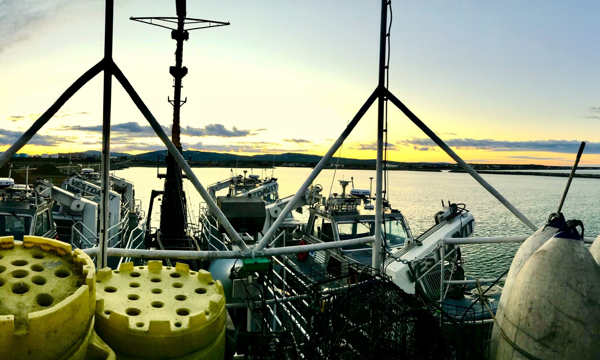
A photo of the Ron Brown off the coast of Grand Bahama Island
The survey team acknowledges and then raises the CTD platform and places it is the water at the surface for a minute or two. Then after receiving a signal from the computer operator that all functions are operating within normal parameters the platform is lowered to 10 meters and held there for two minutes to allow the instruments to stabilize.
Here I am starting my midnight to 6 :00 am shift at the CTD computer control station in the computer lab of the NOAA Ship Ronald H BrownThe "brains" of the CTD. This device also contains the pressure sensor.
After the two minute hold at 10 meters the entire platform is brought back to the surface and the log is started as the package is lowered. The descent begins at about 30 meters/minute and eventually reaches 60 meters/minute. Many of the deep water casts on this cruise were between 4000 m and 5500 meters (about 13000 ft and 18,000 ft) and take over an hour to reach the bottom. While the descent takes place all the instruments are recording data which is stored and plotted in real time at the computer monitor. When the CTD platform is 10 meters from the bottom the descent is stopped and the first water sample is collected by sending a signal that closes the first Niskin bottle. At this point the CTD slowly begins its climb back to the surface (another hour or more) stopping at designated depths to collect water samples.After the last Niskin bottle is closed at the surface, the CTD platform is brought back on deck, the water samples are removed, and the entire platform is prepared for the next cast.
Here I am on the weather deck in my favorite chair on the ship. I enjoy relaxing here in the sun in the morning after a night shift at the CTD computer station.Another beautiful western Atlantic pre-sunset. I enjoyed many of these during the cruise.The early sun rising in the east off the stern of the Ron Brown brings another night of CTD's to an end.
NOAA Teacher at Sea Wes Struble Aboard NOAA Ship Ronald H. Brown February 15 – March 5, 2012
Mission: Western Boundary Time Series Geographical Area: Sub-Tropical Atlantic, off the Coast of the Bahamas Date: February 24, 2012
Weather Data from the Bridge
Position: Windspeed: 15 knots
Wind Direction: South/Southeast
Air Temperature: 23.9 deg C/75 deg F
Water Temperature: 24.5 deg C/76 deg F
Atm Pressure: 1016.23 mb
Water Depth: 4625 meters/15,174 feet
Cloud Cover: less than 20%
Cloud Type: Cumulus
Science/Technology Log
Moving a ship through the water has come a long way since Ben-Hur was chained to a rowing bench as a Roman War Galley slave. I was interested in what systems powered the Ron Brown and Lt. James Brinkley was kind enough to take me on a tour of the ship’s engine rooms.
The Ron Brown has a total of six separate power units. Three of these are V16 (16 cylinders) diesel engines connected to electric generators.
Second Assistant Engineer Jake DeMello sits watch in the entrance to the engine room
These generators produce electricity to run the ship’s electric motors which turn the screws (propellers). In the past the diesel engines would have been connected directly to the propeller shaft, but in the last 20 – 30 years many ships have gone to using electric motors as an interface between the diesel engines and the propellers. On the Brown at any given time two of the V16 diesel engines are online running the generators while the third engine is held in reserve. These generators produce 600 volts of AC current. A transformer converts the 600 V AC to a DC current to run the ship’s large DC electric motors.
Image credit: nauticexpo.com
This image shows a diesel engine connected directly to the “Z” drive.
On the Ron Brown there is a generator and an electric motor between the
diesel engine and the “Z” drive.
A view of the main propulsion diesel engines of the Ron Brown. The V16 propulsion engines are in the foreground while the Ship Services V8 engines are in the backgroundClose-up of two of the V16 Marine diesels on the Ron Brown. For scale notice the flight of stairs behind the engines
Most ships have a propeller shaft that exits the rear of the ship parallel to the keel. The propeller is stationary – it can only rotate to propel the ship forward or backward. To turn the ship a rudder is employed which is usually controlled by a wheel on the bridge. The Ron Brown does not have a rudder; instead it is propelled by a “Z” drive. This type of propulsion system is specially suited for research vessels. In a “Z” drive the main drive shaft from the electric motors comes out parallel to the ship’s keel. It then is joined to a type of “spline gear” and makes a 90 degree turn down. At this point the shaft exits the ship where there is another “spline gear” which turns 90 degrees again parallel to the keel.
NOAA Corps Officer Lt. James Brinkley stands next to one of the V16 "exhaust pipes" from the main propulsion engines on the Ron Brown
The region between the two “universal joints” is mounted on a kind of turn table which allows each of the screws (there are two – one on the starboard side of the ship another on the port side) to rotate 36o degrees. In addition to precise maneuvering, this system of two “Z” drives and a bow thruster, when interfaced with a computer control system and GPS, allows the ship maintain an exact position in the water to within a few feet or better.
The Ron Brown's inboard portion of the "Z" drive. The electric motor that propels the ship is at left. If you look carefully just to the left of center you can see the main drive shaft connecting the motor to the "Z" drive mechanismThe engine status monitor. Notice at the very top it indicates that Propulsion engines 1 & 2 are operating.
The Ron Brown has three other smaller V8 diesel engines that power generators that are used to provide electricity for SS (ship services). This would represent things like radios, heating & air conditioning, lighting, computers, etc. The electricity produced by these three generators goes through two step-down transformers. The first reduction drops the potential from 600 V to 480 V. The next step down brings it from 480 V to 120 V. This is the form that is available to power the equipment throughout the ship. In addition, these three smaller engines and their generators can be used to power the Ron Brown’s propulsion in case of an emergency.
NOAA Corps Officer, Lt. James Brinkley stands next to one of two cable spools, located in the stern of the Ron Brown, that contain 5000 meters of cable each. They are used for long distance towing. For scale Lt. Brinkley is 6'3".
I would like to thank Lt. James Brinkley for the tour and Second Assistant Engineer Jake DeMello for explaining some of the technical aspects of the engines and answering my questions.