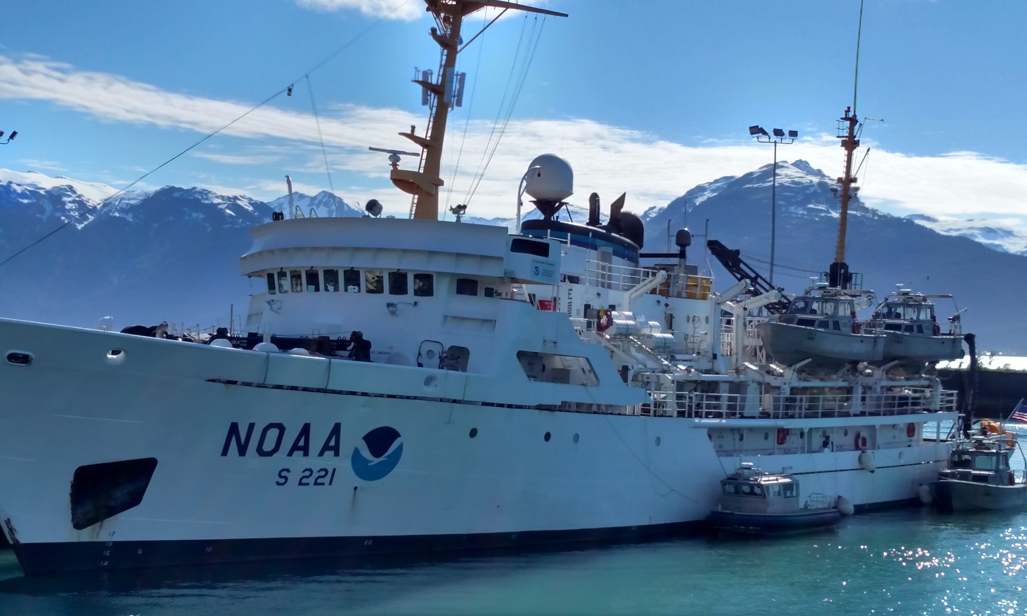
Rosalind Echols: Sound Off! From Noise to Nautical Charts, July 22, 2013

NOAA Teacher at Sea
Rosalind Echols
Aboard NOAA Ship Rainier (NOAA Ship Tracker)
July 8 — 25, 2013 

Mission: Hydrographic Survey
Geographical Area of Cruise: Shumagin Islands, Alaska
Date: July 22, 2013

Current Location: 54° 55.6’ N, 160° 10.2’ W

Weather on board: Broken skies with a visibility of 14 nautical miles, variable wind at 22 knots, Air temperature: 14.65°C, Sea temperature: 6.7°C, 2 foot swell, sea level pressure: 1022.72 mb

Science and Technology log:

Teamwork, safety first
Rainier motto, painted in the stern of the ship above the fantail, the rear lower outside deck where we have our safety meetings.

“Teamwork, Safety First”, is inscribed boldly on the Rainier stern rafter and after being aboard for more than 2 weeks, it is evident this motto is the first priority of the crew and the complex survey operation at hand.

Rainier launch
This is one of the survey launches that we use to gather our survey data. In this case, the launch is shown approaching the Rainier, getting ready to tie up.

It’s a rainy overcast morning here in SW Alaska and we are circled around the officers on the fantail for the daily safety meeting. Weather conditions, possible hazards, and the daily assignment for each launch are discussed. Per the instructions on the POD (Plan of the Day), handed out the previous evening, the crew then disperse to their assigned launches. The launches are then one-at-a-time lowered into the water by the fancy davit machinery and driven away by the coxswain to their specific “polygon” or survey area for the day. A polygon surveyed by a launch on average takes 2-3 hours at 6-8 knots to survey and usually is an area that is inaccessible by the ship. Many polygons make up one large area called a “sheet” which is under the direction of the “sheet manager”. Several sheets make up an entire survey project. Our hydrographic project in the Shumagins has 8 sheets and makes up a total of 314 square nautical miles.

Safety meeting
The CO, XO, and FOO lead the safety meeting for the day, discussing weather conditions, water conditions, and the assignments for each launch.
Shumagin Islands
This is a chart of the Shumagin Islands showing the 8 sheets (highlighted in green) that we are surveying.
Polygons
East side of Chernabura Island divided into survey “polygons”, each labeled with a letter or word. Notice how each polygon is a small subset of the larger sheet.

On board each launch we have a complex suite of computer systems: one manages the sonar, another manages the acquisition software, and the third records the inertial motion of the launch as it rocks around on the water (pitch, heave, roll). The acquisition system superimposes an image of the path of the launch and the swath of the sonar beam on top of a navigational chart within the polygon. Starting at one edge of the polygon, the coxswain drives in a straight a line (in a direction determined by the sheet manager), to the other end of the polygon, making sure there is some overlap at the boundaries of the swaths. He/she then works back in the other direction, once again making sure there is some overlap with the adjacent swath. We call this “mowing the lawn,” or “painting the floor” as these are visually analogous activities. Throughout the day, we pause to take CTD casts so that we have a sound velocity profile in each area that we are working.

Launches
Typical launch dispersal for a survey day. Launches are signified by “RA-number”. You can also see the location of our tide measurement station and GPS control station, both of which we use to correct our data for errors.
Mowing the lawn
This image shows the software tracking the path and swath of the launch (red boat shape) as it gathers data, driving back and forth in the polygon, or “mowing the lawn.” The darker blue shaded area shows overlap between the two swaths. The launch is approaching a “holiday”, or gap in the data, in an effort to fill it in.

You might be wondering, why the swath overlap? This is to correct for the outer sonar beams of the swath, which can scatter because of the increased distance between the sea floor and the sonar receiver below the hull of the boat. The swath overlap is just one of the many quality control checks built into the launch surveying process. Depending on the “ping rate”, or the number of signals we are able to send to the bottom each second, the speed of the boat can be adjusted.  The frequency of the sound wave can also be changed in accordance with the depth. Lower frequencies (200 khz) are used for deeper areas and higher frequencies (400 khz) are used for shallower areas.

Rosalind in launch
Rosalind in front of the computers on the launch, checking for sonar quality (right screen) and observing the path of the ship, to make sure there are no gaps in the data, or “holidays”.

Despite what might seem like mundane tasks, a day on board the launch is exhausting, given the extreme attention to detail by all crew members, troubleshooting various equipment malfunctions, and the often harsh weather conditions (i.e. fog, swells, cool temperatures) that are typical of southwest Alaska. The success of the ship’s mission depends on excellent communication and teamwork between the surveyors and the coxswain, who work closely together to maximize quality and efficiency of data collection. Rain or shine, work must get done.  But it doesn’t end there. When the launches arrive back at the ship, (usually around 4:30 pm), the crew will have a debrief of the day’s work with the FOO (field operations officer) and XO (executive officer). After dinner, the survey techs plunge head first (with a safety helmet of course) into the biggest mountain of data I have EVER witnessed in my life, otherwise known as “night processing”. We are talking gigabytes of data from each launch just for a days work.  It begins with the transferring of launch data from a portable hard drive to the computers in the plot room. This data is meticulously organized into various folders and files, all which adhere to a specific naming format. Once the transferring of data has finished, the “correction” process begins. That’s right, the data is not yet perfect and that’s because like any good science experiment, we must control for extraneous factors that could skew the depth data. These factors include tides, GPS location error, motion of the launch itself, and the sound velocity in the water column.

Plot room
Our chief surveyor works in the plot room cleaning and correcting data.
Data cleaning.
Data showing the consequences of the tide changing. The orange disjointed surface shows the data before it was adjusted for the tide changing. You can see how the edges between swaths (i.e. red and olive green) do not match up, even though they should be the same depth.
Sound speed artifact
This image shows the edge effects of changing sound speed in the water column. The edges of each swath “frown” because of refraction owing to changing density in the water column. This effect goes away once we factor in our CTD data and the sound speed profile.

In previous posts, I discussed how we correct for tides and the sound velocity. We also correct for the GPS location of the launch during a survey day, so that any specific data point is as precisely located as possible. Although GPS is fairly accurate, usually to within a few meters, we can get even more precise by accounting for small satellite errors throughout the day. The Coast Guard provided Differential GPS allows us to position ourselves to within a meter. To get even more precise, within a few centimeters, we determination location of a nearby object (our Horizontal Control, HorCon, Station) very precisely, and then track the reported position of this object throughout the day. Any error that is recorded for this station is likely also relevant for our launch locations, so we use this as the corrector. For example, if on July 21, 2013, at 3pm, the GPS location of our Bird Island HorCon station was reported 3cm north of its actual location, then our launches are also probably getting GPS locations 3cm too far north, so we will adjust all of our data accordingly. This is one of the many times we are thankful for our software. We also account for pitch, heave, and roll of the launch using the data from the inertial motion unit. That way, if the launch rolled sideways, and the center beam records a depth of 30 meters, we know to adjust this for the sideways tilt of the launch.

HorCon station
This shows the set up of our Horizontal Control and tide gauge station. The elevated rock position was chosen to maximize satellite visibility.

After all correctors have been applied (and a few software crashes weathered), the survey technicians then sort through all the data and clean out any “noise.” This noise represents sound reflections on sea life, air bubbles, or other items that are not part of the seafloor. Refraction of sound waves, as mentioned in the last post, is caused by density changes in the water due to changes in the temperature, pressure, or salinity.

Dirty data
This shows sonar data with “noise”. The noise is the seemingly random dots above and below the primary surface. On the surface itself, you can see data from four different swaths, each in a different color. Notice the overlap between swaths and how well it appears to be matching up.
Cleaned surface
This shows sonar data after the “noise” has been cleaned out. Notice how all data now appears to match a sea floor contour.

Many of the above correctors are applied the same day the data is collected, so the sheet manager can have an up-to-date record of the project’s progress before doing final planning for data collection the next day. After a sheet has been fully surveyed and ALL correctors applied, the sheet manager will complete a “descriptive report”, which accompanies the data and explains any gaps in the sonar data (“holidays”) and/or other errors present. This report, along with the data, is sent to the Pacific Hydrographic Branch for post-processing and Quality Control. After that the data is forwarded to the Marine Charting Division where the data undergoes a final set of Quality Assurance checks and is put in a format that can be printed on a paper nautical chart. From acquisition on the launches to publication on a chart, the process can take up to two years! The length of the process is designed to ensure maximum accuracy as many mariners rely on accurate charts for safe navigation.

Personal Log

As the saying goes, “When in Rome, do as the Romans.” One of the attractions of life in Alaska is access to excellent fishing, and a wide variety of tasty fish species. Although I normally consider myself to be a fairly outdoorsy person, thus far in my life this had not extended to the activity of fishing. However, inspired by Avery’s enthusiasm, and her first successful halibut catch, I decided at least give it a try, obtaining an Alaska fishing license and preparing myself for yet another adventure. I am, after all, always encouraging other people to try new things, especially things that make them a bit nervous, so it only felt right to follow some of my own advice. Honestly speaking, though, the thought of catching the fish and then having to deal with the consequences made me a little anxious.

Rosalind with fish
Rosalind with her first ever fish catch, trying very hard to keep her fingers away from the tip of the hook and the very spiny and painful back fin of the fish. Black rock fish have venomous points on their fins.

Fortunately, I had excellent guidance in this activity, setting out with Avery and two very patient crew members, who put up with my initial lack of skill and muscle, and intense enthusiasm about even the smallest jellyfish in the water. I had realized after my shoreline rock verification expedition that pointing at everything in the water and shouting “Look!” was probably not that helpful if we were trying to identify rocks, but here it seemed more appropriate. At least if you think jellyfish are cool. After several lackluster hours, we finally found a spot where a group of Black Rock Fish were schooling, and caught quite a few very quickly. Not surprisingly, the fish aren’t that happy about being caught and flail around a fair amount. Considering that they have pointy, venomous spines in their dorsal fin, it takes great care to get the fish in the bucket without injury, but we successfully managed it.

Rosalind cleaning
Rosalind learning how to fillet a black rock fish. Notice the safe distance between knife and fingers!

Somehow, in all my years of school, I never actually dissected anything, and have always felt a little squeamish around dead animals. However, after helping catch the fish, I couldn’t very well leave my colleagues alone to deal with the arduous task of filleting and cleaning the fish, so I decided to do my best to participate. It actually went much better than I expected, and I learned quite a bit about fish anatomy along the way. For example, fish have an air bladder that allows them to float. They look much less impressively large when this is deflated.

Fish fillets
A sampling of our collection of black rock fish fillets, mid-way through cleaning. I am proud to have contributed to this!

All in all, it was a very satisfying experience. It is nice to be able to say that I have developed a somewhat useful life skill (fishing as well as avoiding my fingers with large knives). Our wonderful cook, Kathy, even used some of the fish for a delicious lunch of fish tacos, which I hope to try to replicate myself some time in the near future.

FIsh tacos
Delicious fish tacos made from Black Rock Fish caught by Rainier crew and Teachers at Sea Rosalind and Avery!

Fun Fact: a fathom, a maritime measurement for depth equal to six feet, was originally based on the distance between a man’s outstretched finger tips. The word itself derives from an Old English word meaning outstretched or embracing arms. Given that we use it to measure depth, it is also interesting to note that it is related to the word to fathom something, or the adjective unfathomable, meaning immeasurable. The word is also related to the phrases “six feet under” and to “deep six” something.

Avery Marvin: Sound Off! From Noise to Nautical Charts, July 22, 2013

NOAA Teacher at Sea
Avery Marvin
Aboard NOAA Ship Rainier (NOAA Ship Tracker)
July 8 — 25, 2013 

Mission: Hydrographic Survey
Geographical Area of Cruise: Shumagin Islands, Alaska
Date: July 22, 2013

Current Location: 54° 55.6’ N, 160° 10.2’ W

Weather on board: Broken skies with a visibility of 14 nautical miles, variable wind at 22 knots, Air temperature: 14.65°C, Sea temperature: 6.7°C, 2 foot swell, sea level pressure: 1022.72 mb

Science and Technology log:

Teamwork, safety first
Rainier motto, painted in the stern of the ship above the fantail, the rear lower outside deck where we have our safety meetings.

“Teamwork, Safety First”, is inscribed boldly on the Rainier stern rafter and after being aboard for more than 2 weeks, it is evident this motto is the first priority of the crew and this complex survey operation at hand.

Rainier launch
This is one of the survey launches that we use to gather our survey data. In this case, the launch is shown approaching the Rainier, getting ready to tie up.

It’s a rainy overcast morning here in SW Alaska and we are circled around the officers on the fantail for the daily safety meeting. Weather conditions, possible hazards, and the daily assignment for each launch are discussed. Per the instructions on the POD (Plan of the Day), handed out the previous evening, the crew then disperse to their assigned launches. The launches are then one-at-a-time lowered into the water by the fancy davit machinery and driven away by the coxswain to their specific “polygon” or survey area for the day. A polygon surveyed by a launch on average takes 2-3 hours at 6-8 knots to survey and usually is an area that is inaccessible by the ship. Many polygons make up one large area called a “sheet” which is under the direction of the “sheet manager”. Several sheets make up an entire survey project. Our hydrographic project in the Shumagins has 8 sheets and makes up a total of 314 square nautical miles.

Safety meeting
The CO, XO, and FOO lead the safety meeting for the day, discussing weather conditions, water conditions, and the assignments for each launch.
Shumagin Islands
This is a chart of the Shumagin Islands showing the 8 sheets (highlighted in green) that we are surveying.
Polygons
East side of Chernabura Island divided into survey “polygons”, each labeled with a letter or word. Notice how each polygon is a small subset of the larger sheet.

On board each launch we have a complex suite of computer systems: one manages the sonar, another manages the acquisition software, and the third records the inertial motion of the launch as it rocks around on the water (pitch, heave, roll). The acquisition system superimposes an image of the path of the launch and the swath of the sonar beam on top of a navigational chart within the polygon. Starting at one edge of the polygon, the coxswain drives in a straight a line (in a direction determined by the sheet manager), to the other end of the polygon, making sure there is some overlap at the boundaries of the swaths. He/she then works back in the other direction, once again making sure there is some overlap with the adjacent swath. We call this “mowing the lawn,” or “painting the floor” as these are visually analogous activities. Throughout the day, we pause to take CTD casts so that we have a sound velocity profile in each area that we are working.

Launches
Typical launch dispersal for a survey day. Launches are signified by “RA-number”. You can also see the location of our tide measurement station and GPS control station, both of which we use to correct our data for errors.
Mowing the lawn
This image shows the software tracking the path and swath of the launch (red boat shape) as it gathers data, driving back and forth in the polygon, or “mowing the lawn.” The darker blue shaded area shows overlap between the two swaths. The launch is approaching a “holiday”, or gap in the data, in an effort to fill it in.

You might be wondering, why the swath overlap? This is to correct for the outer sonar beams of the swath, which can scatter because of the increased distance between the sea floor and the sonar receiver below the hull of the boat. The swath overlap is just one of the many quality control checks built into the launch surveying process. Depending on the “ping rate”, or the number of signals we are able to send to the bottom each second, the speed of the boat can be adjusted.  The frequency of the sound wave can also be changed in accordance with the depth. Lower frequencies (200 khz) are used for deeper areas and higher frequencies (400 khz) are used for shallower areas.

Rosalind working the surveying computers in the launch

Despite what might seem like mundane tasks, a day on board the launch is exhausting, given the extreme attention to detail by all crew members, troubleshooting various equipment malfunctions, and the often harsh weather conditions (i.e. fog, swells, cool temperatures) that are typical of southwest Alaska. The success of the ship’s mission depends on excellent communication and teamwork between the surveyors and the coxswain, who work closely together to maximize quality and efficiency of data collection. Rain or shine, work must get done.  But it doesn’t end there. When the launches arrive back at the ship, (usually around 4:30 pm), the crew will have a debrief of the day’s work with the FOO (field operations officer) and XO (executive officer). After dinner, the survey techs plunge head first (with a safety helmet of course) into the biggest mountain of data I have EVER witnessed in my life, otherwise known as “night processing”. We are talking gigabytes of data from each launch just for a days work.  It begins with the transferring of launch data from a portable hard drive to the computers in the plot room. This data is meticulously organized into various folders and files, all which adhere to a specific naming format. Once the transferring of data has finished, the “correction” process begins. That’s right, the data is not yet perfect and that’s because like any good science experiment, we must control for extraneous factors that could skew the depth data. These factors include tides, GPS location error, motion of the launch itself, and the sound velocity in the water column.

Plot room
Our chief surveyor works in the plot room cleaning and correcting data.
Data cleaning.
Data showing the consequences of the tide changing. The orange disjointed surface shows the data before it was adjusted for the tide changing. You can see how the edges between swaths (i.e. red and olive green) do not match up, even though they should be the same depth.
Sound speed artifact
This image shows the edge effects of changing sound speed in the water column. The edges of each swath “frown” because of refraction owing to changing density in the water column. This effect goes away once we factor in our CTD data and the sound speed profile.

In previous posts, I discussed how we correct for tides and the sound velocity. We also correct for the GPS location of the launch during a survey day, so that any specific data point is as precisely located as possible. Although GPS is fairly accurate, usually to within a few meters, we can get even more precise (within a few centimeters) by accounting for small satellite errors throughout the day. We do this by determining the location of a nearby object (our Horizontal Control, HorCon, Station) very precisely, and then tracking the reported position of this object throughout the day. Any error that is recorded for this station is likely also relevant for our launch locations, so we use this as the corrector. For example, if on July 21, 2013, at 3pm, the GPS location of our Bird Island HorCon station was reported 3cm north of its actual location, then our launches are also probably getting GPS locations 3cm too far north, so we will adjust all of our data accordingly. This is one of the many times we are thankful for our software. We also account for pitch, heave, and roll of the launch using the data from the inertial motion unit. That way, if the launch rolled sideways, and the center beam records a depth of 30 meters, we know to adjust this for the sideways tilt of the launch.

HorCon station
This shows the set up of our Horizontal Control and tide gauge station. The elevated rock position was chosen to maximize satellite visibility.

After all correctors have been applied (and a few software crashes weathered), the survey technicians then sort through all the data and clean out any “noise.” This noise represents sound reflections on sea life, air bubbles, or other items that are not part of the seafloor.  Refraction of sound waves, as mentioned in the last post, is caused by density changes in the water due to changes in the temperature, pressure, or salinity.

Dirty data
This shows sonar data with “noise”. The noise is the seemingly random dots above and below the primary surface. On the surface itself, you can see data from four different swaths, each in a different color. Notice the overlap between swaths and how well it appears to be matching up.
Cleaned surface
This shows sonar data after the “noise” has been cleaned out. Notice how all data now appears to match a sea floor contour.

Many of the above correctors are applied the same day the data is collected, so the sheet manager can have an up-to-date record of the project’s progress before doing final planning for data collection the next day. After a sheet has been fully surveyed and ALL correctors applied, the sheet manager will complete a “descriptive report”, which accompanies the data and explains any gaps in the sonar data (“holidays”) and/or other errors present. This report, along with the data, is sent to the Pacific Hydrographic Branch for post-processing, and in 1-2 years, we will have a corrected and updated navigational chart. During this time the data is reviewed for quality and adherence to hydrographic specifications and then is distilled into a cartographic product (nautical chart) consisting of points, lines, and areas.

Personal Log:

So I am going to hold off in talking about an animal that has recently fascinated me and instead devote this personal log to some cool things I have been doing on the ship.

Most recently I got to be the helmsman and steer the ship. This involved me following orders from the “conning officer” who told me various steering commands such as: “Left ten degrees rudder”, “steady on course 167°”, “ease 5° right”, “helm in auto” (auto-pilot). To acknowledge the command, I repeated what the conning officer said followed by “aye”. For example: “Left ten degrees rudder, aye” or “course 167°, aye”.  When the boat is actually on the course that was requested by the conning officer, I repeated the command with the word “steady”. For example: “Steady on course 167°”

Avery at the helm
Avery at the helm

You might be wondering why all of the commands involve degrees. Well that is because this ship is steered by the rudder, similar to how you manually steer a small sailboat.  So changing the angle of the rudder will change the direction of the ship.  To change this angle, you turn the steering wheel a desired amount of degrees beyond zero in the direction the conning officer instructed.  So if he said “right 5 degrees rudder”, I would turn the steering wheel right, and stop at the 5 hash mark.

Once the boat actually turns 5°, I will make sure I am at the correct “heading” or degree mark that the conning officer instructed.  A heading can be any number between 000-360 (where 000-deg = North, 045 = Northeast, 090 = East, etc.) as this boat can turn in a complete circle and be navigated in any direction.  (There is 360° in both a compass and a circle.)  Once I am steady at the correct heading, I will put the steering wheel back to 0° which means the rudder is completely straight and parallel with the boat. At this point the boat is going straight. If this were a car, you could just stay straight no problem.

But because this boat moves in water and is affected by ocean conditions such as swells, it is easily knocked off course of the heading. So as helmsman I am constantly making tiny adjustments with the steering wheel by a few degrees in either direction to maintain my heading.   This adjustment is done using the steering wheel if I am driving manual, or using a dial on the gear panel if the boat is in “auto” (auto-pilot). Because the ship rudder must “push water out of the way” in order to steer the boat, there is a delay between when I turn the steering wheel to when the ship actually moves that amount of degrees. This is not a car which turns instantaneously by the movement of axles.  So I need to account for that “lag time” as well as ocean conditions and the speed of the boat when turning the ship.  For example, if the boat is going slow (3 knots) and I need to turn quickly, I will have to use a greater rudder angle.  Throughout this process I have several digital screens that show me my current position and course, current heading and desired heading as well as other navigational aides.  When I was helmsman, I was closely monitored and assisted by Jason, a former Navy Chief Boatswain, who is one of the best helmsman on the ship.  To be a good navigator you need to know the fundamentals but you also need a lot of practice and exposure to various navigational situations.

Helm stand
Helm stand

Yesterday, Rosalind and I got to work on deck and help the Chief Boatswain with various deck tasks such as lowering the anchor and assisting with the davit to hoist the launches from their day of surveying out on the water.  Assisting with the job of lifting a 16,000 lb launch with 3 people aboard using the davit winch was by far the most exhilarating experience thus far on the ship. I handled the task with extreme caution. As with being a helmsman, there are many factors I must consider as a davit operator.  For example, if there is a significant swell, I need to be more aggressive with the davit movements to get the boat lifted fast to avoid any excessive swaying in mid-air. Most importantly, I must attentively follow the gestures of the deck boss below who is able to see the launch very clearly and is directing me on every davit movement.  Even an experienced davit operator like Jason, who probably can predict the next davit movement in his sleep, must never assume and then act. He ALWAYS follows the exact orders of the deck officer below because he never knows what they are seeing that he cannot from the above deck.  Overall, with Jason’s close attention and assistance, I think I did a good job of assisting with the davit. The boat made it safely aboard, and my heart returned to a normal beating pattern. 🙂

Operating the crane to get the davit ready to lift the launch out of the water
Getting the davit positioned and ready to lift the launch out of the water.

On a lighter note I learned how to play the good ole’ mariner pastime favorite, Cribbage. Rosalind (the other Teacher at Sea and my delightful roommate) taught me how to play. We had a cribbage tournament here aboard the ship in which about 12 people competed. I did not advance to the finals but had a lot of fun nonetheless.  I am looking forward to gaining more Cribbage strategies so I can be a more competitive player for future matches.

First round of Cribagge tournament
First round of Cribbage tournament

Just for fun:

An adorable sole I caught on the fantail of the Rainer (I released him/her)
An adorable sole I caught on the fantail of the Rainer (I released him/her). 🙂

Fun factoid: A fathom which is a maritime measurement equal to 6 feet, was originally based on the distance, fingertip to fingertip of a man’s outstretched arms. Fathom that!

Avery Marvin: Is it an Island or Just an Ink Blot? July 16, 2013

NOAA Teacher at Sea
Avery Marvin
Aboard NOAA Ship Rainier (NOAA Ship Tracker)
July 8 — 25, 2013 

Mission: Hydrographic Survey
Geographical Area of Cruise: Shumagin Islands, Alaska
Date: July 16, 2013

Current Location: 54° 55.8’ N, 160° 09.5’ W

Weather on board: Overcast skies with a visibility of .5 nautical miles, South wind at 18 knots, Air temperature: 10°C, Sea temperature: 7.2°C, 1-2 foot swell

Science and Technology log: Shoreline Verification

When you think of a shoreline, you might think of a straight or curved “edge” made of sandy beaches that gradually retreat into deeper and deeper water.  In the Shumagin Islands, a sandy cove is a rare occurrence and a place for a beach party! Towering, jagged cliffs patched with Artic moss and blanketed by a creeping fog are the typical “edges” here.  Below the cliffs in the water, lie sporadic toothed rocks and beds of dense rooted bull kelp, swaying with the current. As I sit on the edge of the skiff (small dingy-like boat), which gently trudges along the outside of the protruding rocks, I think to myself “Is this what Ireland is like?” or is this a world unto its own-untouched and solitary? Whatever it is, this place evokes an ethereal mood and you really feel like you are in one of the most remote places in the world.

Rocky shoreline of Nagai Island
Navigating through Bull Kelp bed
Navigating around Bull Kelp bed
Picture of skiff offshore

Remote it is and that is why we are here. These are for the most part, uncharted or poorly documented waters and shorelines and in this post, I am going to talk about the shoreline aspect.  Besides taking bathymetric data (depth data), hydrographic ships like the Rainier must also verify that the shorelines of various land-masses are portrayed accurately and that all necessary “features” are documented correctly on nautical charts.  Features include anything that might be a navigational hazard such as rocks, shoals, ledges, shipwrecks, islets (small islands) and kelp beds. For shoreline verification, a 19 foot skiff is used for maneuverability and shallow water access. This boat will go out during the “shoreline window”, when the tide is the lowest, with the hopes that if there is a dangerous feature present, it will be visible above the water. In the best case scenario, we can investigate the shoreline fully with the skiff before sending in the bigger launches to survey the area with the sonar, so that we know they won’t hit anything.

Shoreline verification crew

Shoreline verification crew. From left: Randy (Coxswain), John (NOAA Corps. Officer), Chief Jacobson (Chief Survey Tech), Avery (Teacher at Sea)
Shoreline verification crew hard at work
Shoreline verification crew hard at work. From left: Randy (Coxswain), John (NOAA Corps. Officer), Chief Jacobson (Chief Survey Tech), Steve (NOAA Corps. Officer)

The main goal of the scientists aboard the skiff is to establish a “navigational area limit line” (NALL). This is a boundary line delineating how far off shore the launch boats should remain when they are surveying.  This boundary line is obtained in one of three ways:

1) presence of a navigational hazard such as a dense kelp bed or several protruding rocks

2) a depth of 4 meters

3) distance of 64 meters to shore

Whichever of these is reached first by the skiff will be the navigational area limit line for the launches.  Here in the Shumagins, kelp beds and rocks have been the boundary line determinant and often these hazards are in water that is deeper than 4 meters because we have been encountering these before we get within 64 meters of the shoreline.

While scientists are determining the NALL, they are also verifying if certain features portrayed on older charts are in fact present and in the correct location. Using navigational software on a waterproof Panasonic Toughbook, they bring up a digitized version of the old chart of a specific survey area. This chart depicts features using various symbols (asterisk=rock above water, small circle=islet). This software also overlays the boat’s movement on top of the old chart, allowing the boat to navigate directly to or above the feature in question.

Shoreline map 1
Shoreline map showing course of skiff, shoreline buffer, and feature for examination.
Shoreline map 2
Shoreline map showing charted location of islet and the actual location of islet determined by the skiff.

If the feature is not visually seen by the human eye or the single beam sonar on the skiff, it will be “disproved” and a picture and depth measurement will be taken of the “blank” location. If the feature IS seen, more data will be recorded (height of feature above the water, time of day observed, picture) to document its existence.  This same verification procedure is used for newfound features that are not present on the old charts.  All of this data is written on a paper copy of the chart and then back in the “dry lab”(computer lab), these hand-written notes are transferred to a digital copy of the chart.

Section of shoreline showing data and notes about specific features in question
Digitized version of notes and data taken at field site Note: Kelp buffer are the large shaded red areas and the smaller red circle is the actual position of the islet
Digitized version of notes and data taken at field site. The black box corresponds to the area from the previous picture above.
Note: Kelp buffers are the large shaded red areas and the smaller red circle is the actual position of the islet. The three southernmost rocks (marked by red asterisks) inside the black box were disproved.

On the two shoreline verification adventures I went on, many rocks and islets were disproved and several new features were found. Most of the new features were rocks, islets or large kelp beds.  It is important to note that if scientists find a new feature which is a serious present navigational hazard (ex. Shipwreck, huge jutting rock or shoal far offshore) it will be marked a DTON (Danger to Navigation) and communicated to mariners within a short time frame. Other less significant features take 1-2 years to appear on updated nautical charts.

For some survey areas, the Rainier uses aircraft-acquired LiDAR (Light Detection And Ranging) to get an initial idea of various features and water depths of a shoreline area. (This is a service that is contracted out by NOAA.) LiDAR data is obtained by a plane flying over an area at 120 mph, emitting laser beams to the water below. Like SONAR, LiDAR measures the time it takes for the laser beam to return to its starting point. Using this measured time and the speed of light, the distance the light traveled can be obtained, using the equation distance = speed*time, accounting for the fact that it travels through air and then water.  Because light travels much faster than sound, the plane can travel significantly faster than a boat and a large area can be surveyed faster.  Unfortunately LiDAR can only be used in clear, calm water because light is easily reflected by various solids (silt in the water, floating wood), specific color wavelengths (ex. White foam on ocean surface) and absorbed by biological specimens for photosynthesis (ex. Surface bull kelp).  LiDAR surveys do reduce the time hydrographers spend at a shoreline site thus increasing the safety and efficiency of an operation.  As with any data acquisition method, it must be cross-checked by another method and in this case because of the obvious downsides, it is used as a guide to shoreline verification.

Map of island showing LIDAR data.
Map of island showing LiDAR data. The skiff does shoreline verification outside the orange line that outlines the island. Everything inside this orange island was surveyed by the LIDAR airplane. The three orange features circled in red on the southeast section of the island, need to be re-surveyed by the skiff. Different colors show various depths. (Green is more shallow than light blue.)

After spending several days “disproving” a lot of rocks and islets that were clearly not present in their identified location, we started to wonder why someone would have thought there was a specific feature there. One possibility is that it was just an ink blot on the original chart, made by accident (from a fountain pen), and then interpreted as a rock or islet in the process of digitizing the chart. It’s better to be safe than shipwrecked! Another possibility is that these features were “eyeballed” in their documented location, and thus were present but just in the wrong spot.  Lastly because of limitations previously mentioned, LiDAR occasionally mis-reports features that are not present. Fortunately, our current survey methods use sophisticated navigational technology and several cross-checks to minimize data errors.

After shoreline verification has been completed, launches can survey the ocean floor (using SONAR) outside the boundary (NALL) that was established by the skiff. Each launch will be in charge of surveying specific polygons (labeled by letters and names). The picture above shows the polygon areas which are outlined in light orange (most are rectangles). I will talk more about SONAR and surveying on the launch in my next post. 🙂

Personal log:

I have been on the skiff two times now helping with the shoreline verification process. After the second time around and a chat with the XO Mike Gonsalves, my understanding of this process is more fine-tuned. It feels good to reach this point and it reminds me of the need to be patient, diligent and okay with the unknown when learning something new. I, like my students, often seek answers and a deep understanding of complex topics immediately and if this doesn’t happen I can get frustrated with myself. I have been more self-forgiving aboard the Rainier because I know I will be exposed to the same topic or process once again either in a different format or with a different set of crew members. I am also surrounded by a group of tolerant people who continually answer my questions with grace and peak my interest with new ideas.  This repetition of content and supportive network is crucial for any learning environment, whether it be on a ship or in a classroom.  Additionally, I have been given several small but important tasks which make me feel like a part of this group and complex operation.  This empowerment inspires me to learn more and continue contributing. Building a successful classroom community is no different than what is going on here on the Rainier. All students need to have a stake in their learning and a purpose for coming to class each day.

One of my small tasks aboard the skiff during the shoreline verification was to take pictures of the various features (rocks, islets etc.) that needed to be examined.  In some cases, it was important to photograph specific biological features that had an effect on navigation.  For example, when rounding the SE side of Chernabura Island we came across a large Stellar Sea Lion rookery inhabiting a small rocky islet. The male proudly stood in the center, surrounded by about 50 females.  As seen in the picture, this was a hefty male who easily weighed upwards of 1200 pounds. (Males can get as big as 2,500 pounds.)  During the breeding season (June-August), the male will fast and often won’t leave his reproductive rookery site. His primary focus is to defend his territory and spread his genes! Even though male Stellar Sea Lions are polygamous, they do not force the females into a harem but rather control the boundaries around their physical territory where within, the females reside.  The most successful rookery territories, not surprisingly are small rocky islands which can remain stable and productive for up to two months.

Stellar sea lion reproductive rookery

After researching about the Stellar Sea Lion, I learned that the western stock which resides in the Aleutian Islands is listed as an endangered species (since the 1970’s populations have declined by 70-80%). The cause for this is complex and has been attributed to a range of factors including: overfishing of sea lion prey (ex. Herring, Pollock), predation by Orca whales, shooting by fisherman, and disease.  Interestingly, a few native Alaskan communities are still permitted to hunt Stellar Sea Lions for subsistence (survival) purposes.

Stellar Sea Lion Range   Note, the two different stocks (Western and Eastern)
Stellar Sea Lion range

Fun factoid: The Stellar Sea Lion was named after the naturalist, George Wilhelm Stellar who first discovered the species in 1741 while part of Bering’s tragic voyage across the uncharted North Pacific.

Avery Marvin: Ebbs and Flows and Puffins! July 11, 2013

NOAA Teacher at Sea
Avery Marvin
Aboard NOAA Ship Rainier
July 8 — 25, 2013 

Mission: Hydrographic Survey
Geographical Area of Cruise: Shumagin Islands, Alaska
Date: July 11, 2013

Current Location: 54° 49.6 N, 159° 46.6 W

Weather data from bridge: 8.7°C, good visibility (6-8 miles), light and variable wind, overcast

View of Bird Island Cove from tide gauge installation point

Science and Technology Log:

Today, Rosalind and I were scientists in the field, helping the ship’s crew install tidal equipment in preparation for ocean floor survey work.  This was a complex process, so we decided to walk you through it in a step-by-step question format.

What does a navigation chart show you?

The image below shows a chart of the area that we are in right now. Our first anchor point was off the north coast of Bird Island in a cove. On the chart, you can see many tiny numbers in the water areas, which represent various depths.  These depths are measured in fathoms (1 fathom=6 feet).  This depth information helps mariners stay in safe areas that are not too shallow. The charts also show known hazards such as sub-surface rocks and ship-wrecks. This chart clearly has a lot of white space, signifying many areas were never surveyed.

Shumagin survey area
Part of our survey area. Notice the white spaces around Bird and Chernabura Islands!

But wait, why are the depth numbers “fixed” on the charts? Doesn’t the water level change with the tides?

Yes! It sounds easy to say, “the water is 10 fathoms deep at this point”. However, water is subject to the gravitational pull of the moon and sun, resulting in various water levels or tides throughout the day.  So the water will not always be “10 fathoms deep at this point.” For navigational purposes, the most hazardous water level is the lowest one, so nautical charts show the depth at the low tide water level.  Depending on the location, some places have two high tides and two low tides per day (semi-diurnal) and some places have one high tide and one low tide per day (diurnal). Here in the Shumagin Islands we are on a semi-diurnal mixed tide schedule (meaning that the two highs and two lows are not the same height).

How do you measure the tides each day?

shumagin_tide_zone
Map of the Shumagin Island-Sand Point Tide Zones. Notice how the eastern Shumagin Islands are 6 minutes ahead of Sand Point.

There are permanent tide measuring stations all over the globe that provide information on how to “correct for” and figure out your local tide conditions. For our case, there is a tide station at Sand Point on Popof Island, which is west from our survey area.  Our survey area is in two zones, one which is in the same zone as Sand Point and the other which is in a different zone. Therefore, we installed a tide gauge in the latter to verify that the tidal times and heights of this zone are accurately predicted by the Sand Point values. According to the current information, it says that in the different zone the tides should occur 6 minutes before the tides in Sand Point and to multiply the heights by 0.98.

A tide gauge is a pretty cool device that works by the laws of physics. It is installed (by divers) on the sea floor near a coast-line, in relatively deep water, so that it will always be covered with water. The tide gauge uses the water pressure above to determine the depth of the water column (density of water and gravity are the important factors in making this calculation). The tide gauge stays in place for at least 28 days (one full tidal cycle), after which there is a record of the water level throughout that time period (as we were gathering data), as well as a rough idea of the tidal cycle each month, ready for comparison to the Sand Point data.

How do you know if the tide gauge is working?

To verify that the tide gauge is working, humans (i.e.: Rosalind and I), take water level  measurements (in an area close to the tide gauge) using a giant meter stick or “staff”. In our case, we recorded the average water level height every 6 minutes for 3 consecutive hours.  This 3-hour data set can then be compared to the tide gauge data set for that same time period, and hopefully they will show similar trends.  

Geiger_IMG_1279 (25)
Mike (XO) and Avery, taking water level data using the staff (big meter stick)
Tide staff
This is the tide staff we used to gather water level data for comparison to the tide gauge.
Map of the Shumagin Island-Sand Point Tide Zones. Notice how the eastern Shumagin Islands are 6 minutes ahead of Sand Point.
Graph showing the water height measurements from the tide staff and the tide gauge. Notice how they appear to be increasing at the same rate! That’s good.

What happens if the survey terrain changes over time? Will that affect the water depth?

The ocean floor is above a liquid mantle, so it is possible for there to be terrain changes and this would affect water depth measurements. Thus, as scientists, we must make sure the location of our survey area is “geologically stable”. To do this, we installed “benchmarks”. If you’ve ever been to the highest point on a mountain in the United States, you might have already seen something like this: they are bronze disks that mark important places, used by NOAA as well as other agencies. We stamped our benchmarks with the year and our station data, letter A-E (by hand! with a hammer and letter stamps!), and installed them at roughly 200-foot intervals along the coastline in what we hope is bedrock. Once they were cemented in place, we determined each benchmark’s relative height in relation to the staff using a survey instrument called an optical level – this process is also called “leveling.” At the end of the survey season, the ship will come back and re-level them. If the area is geologically stable, the benchmarks should all be at the same relative heights to one another as they were when they were initially installed. More so, the scientists will also be very pleased because their ocean depth measurements will be reliable going forward in time.

Stamping a benchmark
Cemented benchmark
A benchmark firmly cemented in place.
Avery cements her first benchmark :)
Avery next to her first cemented benchmark 🙂
Rosalind measuring distance between benchmarks
Rosalind measuring the distance between benchmarks

So what next?

Now that we have completed all necessary pre-survey measurements and research, we are ready to begin surveying the coastline and ocean floor.  Happy Hydro!

Personal log

It’s a pretty cool feeling to know that you stepped foot on an island that hasn’t seen human visitors in 20+ years. It was also refreshing to get off the big boat and head to shore for some science fieldwork. I learned all about tide gauge and benchmark installation.  I had several small but important tasks:

  • stamp each bronze benchmark with year and appropriate code using hammer and metal letter stamps
  • mix up cement batter and add to drilled rock hole and under benchmark disc to secure it in place for years to come (much harder than it looks because the cement was like “oobleck” and not very cooperative)
  • measure distance between each benchmark using extra long tape measure
  • take water level data using staff (big meter stick) in water every 6 minutes
Cool anemome I found!
Cool sea anemone I found!

In between tasks, I perused the tide pools for various critters. I saw a few new anemones and got a great shot of one with my new underwater camera.  I absolutely love tide pooling and could spend most of the day doing it.  I also enjoyed observing the puffins flying in and out of their cliff-side home. They tended to leave the cliff in packs probably to do some offshore fishing for herring and capelin. Upon return, presumably with a belly full of fish, some puffins would fly in large circles near their dwelling a few times before finally landing. This bewildered me. I thought, what a waste of energy! So I researched this and found out the following:  Puffins are much better swimmers than flyers and have poor maneuverability while in the air. They sometimes are involved in mid-air collisions or crash landings into rocky slopes. Thus, they “size up” their landing a few times by circling near it before finally flying directly into their vertical burrow entrance.

Their body is mostly adapted for swimming, with short rigid wings helping them to “fly” underwater, to 30+ ft. depths! They have durable bones that endure pressure changes while diving and their body tissues store oxygen. They use anaerobic respiration for long dives. To waterproof their wings, puffins rub their bill on their oil gland several times and then smear this oil all over their feathers. How cool!

We are seeing a lot of Tufted Puffins out here in the Shumigans because it is breeding season (June-August), the time when they return from lonely open waters to rocky islands to mate and raise young. Puffins are monogamous, usually having one partner for many years. Interestingly, a female puffin only lays one egg, which is incubated for around 45 days! Both parents share incubation and feeding duties. Right on! The chick then stays in the nest for around 45 days until ready to fly. I love puffins! They are not only adorable but very well-adapted creatures.

Tufted Puffin
Tufted Puffin

Fun/sad factoid: Alaskan and Canadian natives made reversible parkas out of puffin skin. When it was rainy out, they wore the feathers on the outside and in cold dry weather, they wore the feathers on the inside. It took 45 puffins to make one parka!

Rosalind Echols: Ebbs and Flows, July 11, 2013

NOAA Teacher at Sea
Rosalind Echols
Aboard NOAA Ship Rainier
July 8 — 25, 2013 

Mission: Hydrographic Survey
Geographical Area of Cruise: Shumagin Islands, Alaska
Date: July 11, 2013

Current Location: 54° 49.6 N, 159° 46.6 W

Weather data from bridge: 8.7°C, good visibility (6-8 miles), light and variable wind, overcast

View of cove
View of our anchorage from the installation point in a sunny moment.

Science and Technology Log:

Today, Avery and I were scientists in the field, helping the ship’s crew install tidal equipment in preparation for ocean floor survey work.  This was a complex process, so we decided to walk you through it in a step-by-step question format.

What does a navigation chart show you?

The image below shows a chart of the area that we are in right now. Our first anchor point was off the north coast of Bird Island in a cove. On the chart, you can see many tiny numbers in the water areas, which represent various depths.  These depths are measured in fathoms (1 fathom=6 feet).  This depth information helps mariners stay in safe areas that are not too shallow. The charts also show known hazards such as sub-surface rocks and ship-wrecks. This chart clearly has a lot of white space, signifying many areas were never surveyed.

Shumagin survey area
Part of our survey area. Notice the white spaces around Bird and Chernabura Islands!

But wait, why are the depth numbers “fixed” on the charts? Doesn’t the water level change with the tides?

Yes! It sounds easy to say, “the water is 10 fathoms deep at this point”. However, water is subject to the gravitational pull of the moon and sun, resulting in various water levels or tides throughout the day.  So the water will not always be “10 fathoms deep at this point.” For navigational purposes, the most hazardous water level is the lowest one, so nautical charts show the depth at the low tide water level.  Depending on the location, some places have two high tides and two low tides per day (semi-diurnal) and some places have one high tide and one low tide per day (diurnal). Here in the Shumagin Islands we are on a semi-diurnal mixed tide schedule (meaning that the two highs and two lows are not the same height).

What are your experiences with high and low tides? What do you notice when you go to the beach? Leave me a comment!

How do you measure the tides each day?

shumagin_tide_zone
Map of the Shumagin Island-Sand Point Tide Zones. Notice how the eastern Shumagin Islands are 6 minutes ahead of Sand Point.

There are permanent tide measuring stations all over the globe that provide information on how to “correct for” and figure out your local tide conditions. For our case, there is a tide station at Sand Point on Popof Island, which is west from our survey area.  Our survey area is in two zones, one which is in the same zone as Sand Point and the other which is in a different zone. Therefore, we installed a tide gauge in the latter to verify that the tidal times and heights of this zone are accurately predicted by the Sand Point values. According to the current information, it says that in the different zone the tides should occur 6 minutes before the tides in Sand Point and to multiply the heights by 0.98.

A tide gauge is a pretty cool device that works by the laws of physics. It is installed (by divers) on the sea floor near a coast-line, in relatively deep water, so that it will always be covered with water. The tide gauge uses the water pressure above to determine the depth of the water column (density of water and gravity are the important factors in making this calculation). The tide gauge stays in place for at least 28 days (one full tidal cycle), after which there is a record of the water level throughout that time period (as we were gathering data), as well as a rough idea of the tidal cycle each month, ready for comparison to the Sand Point data.

How do you know if the tide gauge is working?

To verify that the tide gauge is working, humans (i.e.: Avery and I), take water level  measurements (in an area close to the tide gauge) using a giant meter stick or “staff”. In our case, we recorded the average water level height every 6 minutes for 3 consecutive hours.  This 3-hour data set can then be compared to the tide gauge data set for that same time period, and hopefully they will show similar trends.  

Tide staff
This is the tide staff we used to gather water level data for comparison to the tide gauge.
Map of the Shumagin Island-Sand Point Tide Zones. Notice how the eastern Shumagin Islands are 6 minutes ahead of Sand Point.
Graph showing the water height measurements from the tide staff and the tide gauge. Notice how they appear to be increasing at the same rate! That’s good.

What happens if the survey terrain changes over time? Will that affect the water depth?

The ocean floor is above a liquid mantle, so it is possible for there to be terrain changes and this would affect depth measurements. Thus, as scientists, we must make sure where our survey area is “geologically stable”. To do this, we installed “benchmarks”. If you’ve ever been to the highest point on a mountain in the United States, you might have already seen something like this: they are bronze disks that mark important places, used by NOAA as well as other agencies. We stamped our benchmarks with the year and our station data, letter A-E (by hand! with a hammer and letter stamps!), and installed them at roughly 200-foot intervals along the coastline in what we hope is bedrock. Once they were cemented in place, we determined each benchmark’s relative height in relation to the staff using a survey instrument called an optical level – this process is also called “leveling.” At the end of the survey season, the ship will come back and re-level them. If the area is geologically stable, the benchmarks should all be at the same relative heights to one another as they were when they were initially installed. More so, the scientists will also be very pleased because their depth measurements will be reliable going forward in time.

Benchmark gear
This is the benchmark-stamping set-up.
Rosalind chiseling
Rosalind chiseling away at the rock to ready it for benchmark installation.
Rosalind and Avery with cement
Rosalind and Avery cementing a benchmark in place for posterity.
Cemented benchmark
A benchmark firmly cemented in place.
Rosalind holding stick
Rosalind holding the level rod for the benchmark leveling process. It turns out that it is incredibly difficult to hold 12 feet of leveling rod level.

So what next?

Now that we have completed all necessary pre-survey measurements and research, we are ready to begin surveying the coastline and ocean floor.  Happy Hydro!

Personal log

One of my favorite parts about this particular activity was exploring the coastal wildlife along the way. A Harbor Seal spent a good portion of the day swimming near by and keeping an eye on what we were doing. Unfortunately, every time I tried to get closer for a picture he ducked under water. He was clearly very curious, though. No doubt the installation of the equipment seemed rather bizarre.

Installation point
This is a view of the installation point we used for the tide gauge. You can tell that the tide is low because of all the exposed animal and plant life at the base of the rocks.

Being on the rocky outcropping where we installed the tidal gauge and the beach nearby reminded me a great deal of my childhood. From the washed up bull kelp still clinging to a barnacle (sometimes still alive) to the hermit crabs scurrying away from my hand in tide pools to the brightly colored sea anemones untucking as the tide came in, it brought back a lot of fond memories and definitely re-inspired my childhood enthusiasm for exploring nature and learning about biology by experiencing it. It also brought back that sense of heightened physical awareness as I scrambled from barnacle-covered rock to barnacle-covered rock, trying to avoid the slippery foot placements that would inevitably lead to lengthy gashes on my hands. All is well. I returned from my beach adventure in one very intact piece, slightly rosy-cheeked despite the overcast conditions.

Sea anemone!
An open sea anemone. They also come in red, orange, pink, and purple!
Wildlife!
Sea Anemones, barnacles, and other rock-dwelling critters exposed at low tide.

Aside from that, as someone who loves food and eating, the Rainier has treated me very well so far. We have some wonderful stewards and cooks, who do a far better job feeding 50+ people than I do feeding one or two. Every meal includes several gourmet options, including stuffed peppers, chicken or tofu stir fry, braised beef, and countless other delicious things. And there is dessert at every meal. And a freezer full of ice cream. No wonder the crew on the Rainier seems so happy!